
Merlin
I am assuming that your omega is the spring constant of the rod. It appears to be changing directly proportional to the different mass between states?
The damping co-efficient has also lost a square root.
I did put away a good bottle of red wine last night but I must admit to being very confused now. The logic seems to follow that the mass of the fly line has no effect on damping ratio. If I put a 10 weight line on a 2 weight rod it would be severely damped.
regards
Vince
Just twigged as I was posting at the same time as Gordon that we are not using drag in the same manner. I automatically default to the aerodynamic form due to my day job.
PLEASE NOTE: This is the Archived Sexyloops Board from years 2004-2013.
Our active community is here: https://www.sexyloops.co.uk/theboard/
Our active community is here: https://www.sexyloops.co.uk/theboard/
SHO model trends - what we can get from it
-
gordonjudd
- IB3 Member Level 1
- Posts: 2214
- Joined: Mon Jul 10, 2006 12:14 am
- Location: California
- Contact:
I hope I do not come across as trite because that is not my intention. I am getting a bit frustrated at the internet as a medium to explain complex ideas. I like drawing pictures on boards.
Vince,
You do come across as polite, however, and that seems to be a rare commodity in these discussions as well. Thank you for asking some questions that people who may have a fear of being wrong are afraid to ask. This stuff is a lot more complicated than just being a matter of "high school physics" as Lefty is fond of saying. For example, very few people seem to understand Merlin's model, since it involves an ODE.
Merlin has been looking at the dynamics of casting forever, and I have studied it since reading Dr. Robson's paper in 1990, so it may take a while for you to read some of threads involving Merlin's and Grunde's forced harmonic oscillator model. I expect it will be more than a one bottle of wine project.
There are some details on the ODE that is being used in that model here.
Your comment preferring a white board conference to share technical ideas is well taken. I go back to the blackboard days, and am thankful for the patience senior engineers at Hughes had in explaining technical concepts to me. It is a pity that we cannot get together and do the same with people from all over the world who are interested in the physics of casting.
Theoretically it is possible and Gordon would recognize a band pass filter. I do not know how you would do that on a fly rod.
We are forcing the rod with a broad band acceleration function rather than a single sinusoid that is used to to look at forced harmonic oscillators. Thus I do not think you are going to "excite" a single harmonic mode in casting, but a composite of vibration modes will be excited at the stop. Even though you may generate higher frequencies, I don't think they are going to have much of an effect on the line speed, and as Tom found the phasing of the second mode may actually decrease the tip velocity at RSP1.
As Merlin has pointed out the effects of higher modes on line speed are going to be insignificant, although bringing it up does show you are aware of the more complicated behavior of a flexible rod.
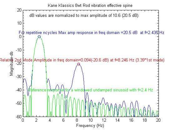
If you built your model and forced it, you would see harmonics at 6.2 and 9.3Hz on a spectrum analyzer.
The harmonics of the oscillating frequencies of a clamped rod are more complicated than the harmonics of a string. Thus the second harmonic of the rod is around 3.3 times the fundamental and the third is around 9 times the fundamental, not the simple factors of 2 and 3 that you get for a vibrating string.
If you can excited them in a clamped rod, they do show up at different levels that are much smaller than the fundamental mode. I have only seen the third harmonic show up once doing that test, otherwise it gets buried in the noise of the spectrum plot as shown below.
Gordy
"Flyfishing: 200 years of tradition unencumbered by progress." Ralph Cutter

Yes, Gordy, it would be more appropriate to introduce a damping function using the square of velocity, but this would limit the resolution to numerical modeling. Using the traditional damper is a shortcut indeed, but it is quite fair if you stay within a limited domain, and this is why I often speak about fishing conditions for the model and not distance conditions. Until now the checks which have been made show that this shortcut remains acceptable.
Vince, I do not think there is a square root missing, omega is the square root of K (rod stiffness) / m (load including the rod mass). If you compare numbers, let’s say that m line = 4 times mo (equivalent rod mass at the tip, a few grams) and thus the damping coefficient in state 1 corresponds to 5 times the mass of state 2 and half the value of omega ( = 2 pi * frequency). In this example, that means that the damping coefficient Cv1 = 2.5 Cv2 approximately:
Cv1 = 2 zeta (m line + mo) * (1.2*2pi) and
Cv2 = 2 zeta (mo) * (2.5*2pi)
So the importance of the losses are larger for state 1, which is desirable to take the line on board, and this is why, partly by chance, there was no need to change significantly the value of zeta. A pragmatic approach as you can see. The zeta value I am using has been obtained by experiment looking like state 2, mine was derived from a measurement in the lab of Noel Perkins. I use it also for state 1, bearing in mind the numerical example above, as an estimate for modeling that state. For the time being, it looks fair enough.
What you call “severely damped” by changing the mass of line comes mainly from the fact that the rod slows down under the effect of load. That would logically mean there might be a need to adapt zeta if the drag conditions can be considered significantly different. If we can get an evidence of that through an experiment, and the way to estimate it, then I can change the zeta value for state 1 condition accordingly, but that would not change the story for state 2.
Again, the driver in the model remains the loaded frequency of the rod (speaking about max line speed).
Merlin
Fly rods are like women, they wont´play if they're maltreated.
Charles Ritz, A Flyfisher's Life
Charles Ritz, A Flyfisher's Life
Thank you for the welcome and if you are looking for someone to ask obvious questions, then you've come to the right person. 
For the harmonics, I can see that I went for the simplistic answer without considering the input. I started life as a radar technician and recall the frequency spread of a square wave.
I would still be looking for 2 values of zeta. The slowing of the rod( reduction in frequency) is what I would expect to see as the damping ratio increased. You can see it in the wikipedia chart that Gordon posted at Post 97. The zeta load for the 1st condition is good
By drag I take it you mean increased load?
By equivalent tip mass, does this mean that you consider acceleration?
-
gordonjudd
- IB3 Member Level 1
- Posts: 2214
- Joined: Mon Jul 10, 2006 12:14 am
- Location: California
- Contact:
By drag I take it you mean increased load?
Vince,
No the increased load (mass of line) will reduce the loaded frequency of the rod/line, but its length impact on the aerodynamic drag is not included in the model. The damping factor used from RSP0 to RSP1 is only related to the frictional losses in the rod. That factor (.01 to .03) is so small that it has minimal effect on response of the rod.
Grunde did not include any damping in his car/spring/brick version of the model, and yet got very similar results to the ones predicted by Merlin's finger/spring/marble version that uses the same ODE approach to the problem.
After the line mass is assumed to be decoupled from the rod at RSP1 (in reality it is later than that) just the mo (effective mass) of the rod and the increased damping from the caster relaxing his grip is used in the model to approximate its counterflex response from RSP1 to RSP2. We have to put in overdamped values (Merlin's value of 18 corresponds to your value of 18/omeg_0 so a damping coefficient of around 6) to get the smaller counterflex deflections that you see in an actual cast.
My personal view is that shows that with enough degrees of freedom in a model you can use it to approximate a measured response even though the overdamped value of 6 may not have much to do with what really goes on. Remember this is a simple one dimensional model that is trying to predict (or match) the deflections and line velocities we measure for a much more complicated 2-D or 3-D problem.
There are aerodynamic drag (both form and tangential drag components) losses on the line and rod in the real world, but they are not (as yet) included in the model.
By equivalent tip mass, does this mean that you consider acceleration?
The angular acceleration of the rod butt is the forcing component the rod is responding to as described in the description of the extended model.
The effective mass is just a term that is used in the model to determine how the loaded frequency of the rod will vary with different tip loads.
Its value is related to the moving mass in the rod that impacts the KE from rod's spring velocity. The details how it relates to the mass distribution in the rod and the mode shape of the fundamental mode is described here.
Keep asking pertinent questions.
Gordy
"Flyfishing: 200 years of tradition unencumbered by progress." Ralph Cutter
Thanks Gordy
This is now becoming a 2 bottle of wine problem but my wife is away at her mothers and the rivers open here tomorrow.
I did not think aerodynamic drag would be included in the model but for an aerosystems engineer it is intuitive to make that association with the term.
Because of the history of the model, I have assumed that the problem with the low damping ratios is something to do with this afternoons analysis. I wanted to understand mo before making any sweeping statements and needed to be comfortable that it was an apples and apples comparison we were making.
You mention that mo relates to a moving mass but I think that the mline = 4xmo comparison is made against a static line mass. If that is the case, then we may have solved the damping ratio
Good morning Merlin
I have a little while for the sun to burn the frost of the ground before I go fishing.
I think that to include mo and mline together, mline also needs to be considered as a moving body.
I was thinking about the qualities of mo and that it has reactive rather than resistive properties. If so, the the system is acting as a tuned mass damper but I cannot yet see what we are tuning for apart form critical damping. I think that in your graphs in post 98, we should be aiming for the maximum value in the 1st peaks that corresponds with the minimum values in the 2nd peak.
A better summary might come to me while I fish

Hope fishing was good, Vince
The purpose of my example (m line = 4 times mo) was to give orders of magnitude, of course the line is considered as moving with the tip of the rod...
The value of mo is small (e.g. 3 grams) and is a reflect of the dynamic behavior of the rod. Gordy used the words "the mass in motion" and it is the right expression. A rod vibrates as if only mo was at the tip top (forget its actual mass for a while). It was detailed in another thread last year if I remember well.
Maximum counter flex corresponds nearly to the highest line speed tuning, and there is not a straightforward link with maximum rod deflection. Rod deflection can increase after you pass the maximum line speed tuning point, while counter flex is reduced at the same time.
If it was straightforward, we would easily understand how a SHO works :glare:
Merlin
Fly rods are like women, they wont´play if they're maltreated.
Charles Ritz, A Flyfisher's Life
Charles Ritz, A Flyfisher's Life
-
gordonjudd
- IB3 Member Level 1
- Posts: 2214
- Joined: Mon Jul 10, 2006 12:14 am
- Location: California
- Contact:
I was thinking about the qualities of mo and that it has reactive rather than resistive properties. If so, the the system is acting as a tuned mass damper but I cannot yet see what we are tuning for apart form critical damping.
Vince,
What is the difference between a reactive and/or a resistive property when it comes to mass?
Also damping has a very minor effect on the way the rod unloads from MRF to RSP1 so your reference to a "tuned mass damper" is a bit mystifying to me. To first order the rod/line system it is acting as a forced harmonic oscillator, but it seems very few people understand what that means.
A rod vibrates as if only mo was at the tip top (forget its actual mass for a while). It was detailed in another thread last year if I remember well.
Did you understand the mo thread that Merlin referred to in his post? Mo is just taking into account that the rod is not an massless spring as generally assumed as a simplification in most dynamics problems involving ideal springs.
The impact the mass of the spring has on the oscillating frequency of a SHO for different masses is discussed at about 27:00 minutes into this MIT lecture by Dr. Lewin. He stumps his students about this difference between the measured and expected frequency for an added mass at about 32 minutes into the lecture. Bill Gates says he admires Dr. Lewin's ability to describe complex concepts, so viewing some of his lectures is a very worthwhile enterprise if you can find the time to do so.
His mo=(mass of spring)/3 factor is the value you get for a linear spring. Our situation is more complicated because both the mass distribution in the rod and the velocity profile of the rod are non-linear functions. Consequently the process to find the mass divisor factor for a fly rod requires a numerical solution and generally gives values of 12-20 vs the value of 3 you get for a linear spring.
To me mass is mass. It is just the factor that involves the force it takes to change the momentum (any change in mass, speed or direction) of an object. As described in Wikipedia.
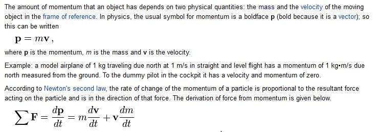
That second v*dm/dt term is important in determining the acceleration force on the fly leg of the line that comes from the change the amount of moving mass in the line as the loop propagates.
If you use the high school version of Newton's second law ( which only includes the first m*dv/dt term or F=ma) you would not get the right answer since that equation assumes the mass is constant and only the velocity is changing (a=dv/dt).
Gordy
"Flyfishing: 200 years of tradition unencumbered by progress." Ralph Cutter
Today I lost a battle of wits and reaction to a fish. Very odd start of season conditions, blue skies, warm air and cold water about 18 inches lower than usual. I could rise the occasional brownie but was too slow.
My apologies to you both for this mornings post it was a half formed thought and I should have just written a note. I had the joys of bacterial meningitis a few years ago and struggle with short term memory. Since then I am in the habit of jotting thoughts down before I lose the train of thought.
I am happy with the mass and momentum side of things but misunderstood the x3 because my wet finger calculations put the multiple at about 10-12.
I did understand the Mo link but went off on a tangent thinking about the fact we have a non-linear response and that the system behaves like an LRC circuit, instead of an LC circuit. I'm guessing that is what you meant by the Dr Lewin lecture (apologies it is on my to do list).
I have seen this sort of response before in a tuned mass damper, I mentioned it in an earlier post about helicopter vibration. A tuned mass damper is a SHO with 2 masses and 2 springs:
http://en.wikipedia.org/wiki/Tuned_mass_damper
While it has a lot in common with the stage 1 model construct, I have only seen them used to suppress a potential resonant frequency and wanted to kick the idea about a bit as I have heard of peak frequency response but have never seen it used:
Consequently, this has also been added to my reading lilts:
http://www.math.usma.edu/people....-30.pdf
My apologies again, I'll wait before posting next time.
regards
Vince
-
gordonjudd
- IB3 Member Level 1
- Posts: 2214
- Joined: Mon Jul 10, 2006 12:14 am
- Location: California
- Contact:
My apologies again, I'll wait before posting next time.
Vince,
You have nothing to apologize for.
As you said this would be much easier if we were drawing pictures on a whiteboard. I have been proven wrong many times, and am old enough that it does not phase me. I am just trying to get a better understanding of the physics of casting, and I think your engineering experience will help that along.
I will take a look at your tuned mass damper, but just from the sounds of it, I think it is much more complicated than Merlin's finger/spring/marble model that has given some very useful results in looking at different casting scenarios like the ones in this thread.
Gordy
"Flyfishing: 200 years of tradition unencumbered by progress." Ralph Cutter
Thanks Gordy
I'm still trying to understand the shape of the problem and do not believe that I have any answers. Although the tuned mass damper is more complex than the SHO model, I am hoping to be able draw some principles from it. The discussion around maximum response amplitude and its relationship with damping is tantalizing for me but my math skills are ring rusty
regards
Vince
Merlin
This was opening day on my home water:
http://davewiltshireflytying.blogspot.co.uk/
I went out the next day and took 3. It was all about presentation
Gordy
Under what conditions did you measure your Kane Klassics at post 107. Did you have an external mass at the tip or were you measuring unloaded frequency?
regards
Vince
-
gordonjudd
- IB3 Member Level 1
- Posts: 2214
- Joined: Mon Jul 10, 2006 12:14 am
- Location: California
- Contact:
Under what conditions did you measure your Kane Klassics at post 107. Did you have an external mass at the tip or were you measuring unloaded frequency?
Vince,
It was an unloaded or natural frequency measurement.
I have found that the magnitude of the second (or third) modes are greatly reduced when there is a tip load attached to the rod as it is vibrating.
Here is a frequency domain plot of that same rod with a 10 g tip load.
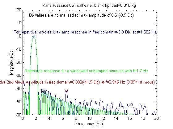
You can see the second mode amplitude was only .8% of the fundamental for that case, and thus it was barely above the measurement noise.
It appears it also increased the ratio of the second mode vibration frequency to the fundamental. As noted on the graph that ratio was around 3.9 with the 10g tip load vs 3.4 for the no load case.
Gordy
"Flyfishing: 200 years of tradition unencumbered by progress." Ralph Cutter
Who is online
Users browsing this forum: No registered users and 1 guest