Wow, I've not logged in for a long time, I believe the last PM dates back to 2009
I've found some stuff that I've written 2008/2009 - something that you perhaps like. It's a fly line simulation algorithm.
Simulation of a fly line is not an easy task, because the a fly line is relative rigid in one dimension and thus you're ending up with stiff differential equations. So you need an implicit solver and something for nonlinear equation systems.
However I've managed these challenges and found the results not that bad. The fly line is modelled as a chain of cylinders, I've added simple models for the internal forces (linear springs, torsional springs) and external forces like the air friction.
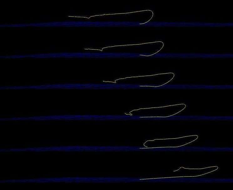
I've attached a picture series of one simulation run. You can see here the typical "dip" of the leader (Grunde's movie has shown that) and the nose shaped loop.
I hope I can find this winter some time to work further on that tool .
Bye,
Torsten
Attachments
SimulationRun.jpg (55.44 KiB) Viewed 4065 times
^^ Warning: The above text contains misspellings, grammatical errors and of course nonsense.
really good to see you back on the forum! The images from your simulation looks impressive, and I look forward to learn more about your simulation model. I also believe that your work will allow us to answer many questions on line/loop propagation and the dynamics of fly casting. (And maybe we should finish our little note on line tension and loop propagation? )
Cheers,
Grunde
"Essentially, all models are wrong, but some are useful."
George E. P. Box
I hope you've got a comfortable seat, I've got a lot of questions
I'd also be interested in the dangle mechanism and the development of your work with Grunde on tension. I found a paper on low tension cables that indicated a potential cause of the dip but the maths defeated me.
From my limited knowledge of the dangle, Vince, it's a transverse wave that runs down the fly leg, either as a result of line configuration on the backcast, or more usually the tip rising at the beginning of the casting stroke. I imagine that the physics are exactly the same as tailing loops propagation. I'm sure the dangle could/can be avoided, but at the expense of casting arc.
Of course I could be completely wrong, and not for the first time!
Hi Torsten and welcome back ,
can your model calculate the relationship between tip path and the loop that will result in a two dimensional perspective?
Looks pretty interesting.
Not sure yet, what datas you feed the box with to get the output?
Best
Bernd
This is part of the summary of Doctoral disseration on the dynamics of a low tension cable:
The mechanisms for low-tension response to excitation are explored by considering the limiting case of a cable with zero initial tension, subject to an impulsive force at one end.
The three-dimensional equations show the development of impulsive tension. The intensity of the tension and the velocity components depend exclusively on the initial curvature and are independent of the geometric torsion. In addition, singularities are found to develop at points of curvature discontinuity. Incorporating the cable's bending stiffness removes these singularities by ensuring smooth curvature. However, sustained boundary layers are found to develop, demonstrating the importance of the underlying physical mechanism.
The transition from taut to low-tension behavior is examined through an analysis of the dynamics of a hanging chain, driven by planar harmonic excitation at the top. For moderately large excitation amplitudes, asymptotic results demonstrate the existence of distinct
regions of stable two-dimensional and stable three-dimensional response, as a function of frequency, as well as a distinct region in which all steady state solutions are found to be unstable. Numerical solutions of the fully nonlinear equations are in close agreement with the asymptotic results.
Numerical results for even larger excitation amplitudes show that large impulse-like tension forces develop which cause the chain to lose tension over a region adjacent to its freely hanging end, and then collapse. The transition from low to high tension regions is clearly demonstrated, with low tension effects being confined to the lower portion of the chain.
The bit in bold caught my eye. Its a monster paper but I'm happy to pass it along, although it looks like Torsten has already solved it.
regards
Vince
PS If you scroll up and down fast, you can animate Torstens graphic :laugh:
Ok that's a completely different proposition! It would be interesting to have the line configuration in the first of Torsten's simulation start with an inverted curve.
Is this why a towed untethered rope "flaps" or is flap a different phenomena?
These models also largely neglected many of the factors the New York team considers to be instrumental in the effect, such as the tension, elasticity and mass of the flapping material. The transition point between the flapping and non-flapping states, for instance, appears to be when the elastic energy of the thread is matched by the kinetic energy of the flow.
Thanks for the feedback.
The bad thing is only that I've forgotten most of how I've implemented it back then. I've to clean up the whole thing and have to relearn the theory .. this will take a while.
@Grunde Yes, I remember there was something I'd say I'll get first the simulaton core running that I can compare the theoretical result with the simulation. Computing the tension should be quite easy.
For the algorithm I'm splitting the line into a chain of cylinders - the cylinders itself contain a one dimensional spring and there is a torsional spring between each cylinder. There are several external forces acting on each cylinder caused by gravity, air friction etc.
The simulation requires the tip path and the velocity of the tip along this path. There is a little trick used for this purpose: the first point of the line has an unlimited mass and I specifiy simply the trajectory of this point. Later the full rod could be included into the simulation. Currently it's 2D only but I'll extend it to a 3D coordinate system. Hope This answers Bernds question.
@Paul I'm well, thanks - I'm just working too much.
I think Paul is right; the dip has very much to do with the moving direction of the tip and the initial placement of the line. It took me also a while to get a useful tip trajectory for a nice loop.
Bye,
Torsten
^^ Warning: The above text contains misspellings, grammatical errors and of course nonsense.
Torsten,
It is great to have you contributing once again.
This will be a great tool and it looks like it does an excellent job of modelling the loop morph we see in casting.
What values are assuming for the skin and form drag coefficients? If you force them to go to zero do you see the same kind of loop morph into a climbing loop shape or is drag the source of those changes?
Did you have some fly drag included to keep some tension at the fly end of the line?
What produced the transverse wave that appears to produce the dangle in the sequence below:
Terrific work. Thanks for sharing it.
Gordy
"Flyfishing: 200 years of tradition unencumbered by progress." Ralph Cutter
I think I've taken the values for skin friction and form drag from a Noel Perkins paper, but I've to check this. And yes, these forces had a big influence on the loop shape. Basically the loop morphing is mainly because of the form drag.
I believe I've modelled already the fly drag; but I'm unsure if that was for the above simulation run. The leader looks really a bit unstable and undamped. This explains perhaps the wave. I'm also not shure if I've set the line stiffness high enough, looks pretty like a very limp line to me.
BTW The loops look really funny with a "stiff" line.
@Hal
This run used 200 elements; there was a trade-off between numerical stabilty and computing time. I'll try then if I can raise it much further.
Bye,
Torsten
^^ Warning: The above text contains misspellings, grammatical errors and of course nonsense.