Remember the debate on the possible ovalization of rod sections under bending? If you don’t, the issue was that thin walled structures (hollow tubes) can ovalize under bending, up to the point they collapse (some of us have experienced bending a copper tube at a square angle while plumbing in our house I guess). Even if rods do not completely collapse, sometimes some break, and this can be due to a local collapsing (buckling) condition.
Ovalization is a reaction of a structure minimizing its energy content induced by the forces that make it bend. The main consequence is a lower capacity to withstand load, it can fail below the maximum allowable stress of the material. Ovalization has an effect on the stiffness of the structure and the question was to know if it exacerbates the bending amplitude in real life conditions and by how much. Some rod makers say ovalization is real; some say it is a thing of the past, so let’s test the idea.
A first point is that our rods are not extremely thin walled, only glass rods may be qualified as such, the ratio of their radius divided by their wall thickness can go beyond 10 in the butt. For graphite rods, it can be half of that, but for really thin structures, one speaks of ratios like 50 to 100. In the tip our fly rods, this ratio is even smaller. In such condition, a reasonable assumption is that ovalization of fly rods might not be significant. However, we were heavily arguing about that on the forum last October, so to clarify the situation, I decided to require the help of a massive calculation weapon.
Thanks to my professional relationships, we can benefit from the calculation made with the top of industry professional software, ABAQUS, currently used for structural engineering in aircraft and auto industry (and in many other areas). My deepest thanks to the computing center who accepted to run that monster for peanuts.
I used a simplified rod design (straight profile) and graphite characteristics which existed already 20 years ago (rather low modulus, high resistance, data were taken from professional literature). The rod is represented by a beam having “orthotropic” characteristics which is typical of unidirectional graphite including a glass scrim. If you think of hoop strength, it is very small for such a rod so we are on the “worst side” scenario.
There are two cases under study: (A) the rod is horizontal and loaded with 300 grams at the tip, and in the second case (B) the rod makes a 45 degrees angle above horizontal with the same load, as in the test conducted in the Yellowstone angler rod survey. The idea was to achieve some 50% relative deflection of the rod, something on the high side in fly rod normal usage. The results show relative deflections of respectively 52% and 60%, so we are on target.
First analysis: the global deflection under load in both cases. My own data corresponds to the red curves. ABAQUS data are represented by the green curves.
The differences are not large, 3% to 4% for the deflection perpendicular to the butt direction. The differences are higher in the direction parallel to the butt (3% to 7.5%). Given the fact that my model gives estimates within 1% at 35% deflection, we could consider that ovalization occurs from that point, and could have a small impact for 50% deflection; and a larger but limited one for 60% deflection. So let’s have a look at it.
Second analysis: the ovalization data. Well, 2% or 0.02%? None of these, but something like 0.2%.When I saw the results, it was clear that I had an order of magnitude difference with reality (too small estimates). You can see that after an arbitrary correction by a factor 10 which is illustrated here, the values (dotted blue curves) are close to those coming from Abaqus (green curves), especially far from the embedment. I don’t know where the bug is and I have to investigate. Hope I can find it someday.
In the deflection profiles I compute, there is no ovalization, I just derive an estimate of it but do not compute the extra deflection due to ovalization. For ABAQUS, everything is included so the differences integrate the ovalization and the potential lack of fit of my model under equivalent assumptions.
Conclusion: ovalization is real, but remains small, even for a structure which has no hoop layers as the one used here. So modern rods fitted with hoop fibers have potentially very small ovalization capacity. On top of that, the model rod is idealized (1 single section). The ferrules of our usual 4 piece rods act as stiffeners and are counteracting ovalization in practice. To me, this study shows that our current modern rods may exhibit a very few extra % of deflection due to a small ovalization, and this will happen under extreme conditions.
Comments are welcomed
Merlin
Fly rods are like women, they wont´play if they're maltreated.
Charles Ritz, A Flyfisher's Life
I used a simplified rod design (straight profile) and graphite characteristics which existed already 20 years ago (rather low modulus, high resistance, data were taken from professional literature). The rod is represented by a beam having “orthotropic” characteristics which is typical of unidirectional graphite including a glass scrim.
Merlin,
What did you assume the E_t and E_l values were for your orthotropic material example? What does "resistance" relate to?
Did the coefficient that relates the amount of ovalization to the variable strain.^2*r_outside/thickness values remain constant over the length of the rod?
If the relative semi-minor axis was reduced to .998 due to ovalization did the relative semi-major axis increase to 1.002 so that the circumference remained the same when measured in a plane that was perpendicular to the curved bending axis?
Would you expect a maximum reduction in the area moment of .9967 at the butt (.33%) to produce a 3% increase in the perpendicular tip deflection? Or was that deflection difference due to differences between the values produced by your FEM model versus the more exact Abacus software?
Gordy
"Flyfishing: 200 years of tradition unencumbered by progress." Ralph Cutter
I am on the way for better estimates by changing my computation strategy with encouraging results (the order of magnitude of ovalization is correct now). I tried to inject the change in section inertia in my model and it just gives nothing substantial. It is likely that the differences I see between Abaqus and my model are basically due to the modelling assumptions: I cannot take section deformation or shear stess on board while Abaqus does, and this might well explain a significant part of the difference.
Unfortunately, there is no way for me to directly compare with Abaqus because I am stuck to Euler assumptions.
Nevetheless the experience is really interesting.
Merlin
Fly rods are like women, they wont´play if they're maltreated.
Charles Ritz, A Flyfisher's Life
Merlin,
Did not expect to see more than single digit percentage differences due to ovalization.
The difference is magnified in total displacement due to the location in the butt.
Are you aware of how the blank was restrained and the load applied ?
Why the use of a linear taper ???
I feel much more may be observed versus real life if even a dual taper is utilized. Possibly 1/3 butt 2/3 tip.
I tried to inject the change in section inertia in my model and it just gives nothing substantial.
Merlin,
Does that mean the deflection due to the inertial loading of the rod due to its mass distribution is quite small?
Thus if you add that inertial loading value to the deflection given by the Euler model for the 300 gram tip mass it still does not produce the 3-4% larger deflection values you are getting with the Abacus software?
Can the mass loading of the rod be roughly taken into account by increasing the tip load by the effective mass value that is around 3 g for fast 5 wt rods?
Gordy
"Flyfishing: 200 years of tradition unencumbered by progress." Ralph Cutter
gordonjudd wrote:Can the mass loading of the rod be roughly taken into account by increasing the tip load by the effective mass value that is around 3 g for fast 5 wt rods?
I would like to follow this. However, I am still waiting for someone to tell me what a 5 wt rod IS and how is different from a 4 or 6 wt rod.
Now, you are talking about fast and slow rods. How fast is a fast rod and how do you determine what it is.
The difference is magnified in total displacement due to the location in the butt.
Well, not that sure, this difference is more likely due to the “rigid” rod description with Euler assumptions by comparison to the theory used by Abaqus which takes all parameters under consideration (e.g. not in plane rotation of section).
There are three potential sources for differences:
1) The rod description (mesh), which is far better for Abaqus
2) The assumptions used for calculations (Euler vs theory used in Abaqus)
3) The potential effect of ovalization
This is why I tried to see if the change in section inertia due to ovalization had an influence, but it is so small it does not. So the suspects are the assumptions and the mesh.
I used a simple taper to simplify the work for the computing center (and mine too). It did not cost me anything at all so I did not want to bother them with a complex rod design.
Gordy
All is included, external load and rod inertial loading. Now I just realized that there was a difference in Modulus between Abaqus and my model (151 GPa for Abaqus and 157 GPa for me), so I just corrected that stupid mistake from my side and here all the data.
Differences observed: 2% in both X and Y directions for the perpendicular case, 5% in X and 1% in Y directions for the 45 degrees study case. Considering we roughly have 3% error on average, the question is: how much for the mesh, how much for Euler assumptions and how much for ovalization?
Too good for ovalization this time, it just looks like a miracle! To find correct ovalization values one has to solve a cubic equation, so for my model, it just means 50 equations for a single run… Now if I introduce the ovalization effect in calculation I do not find any effect on deflection (third digit), so I suspect we face the assumptions and the mesh effects.
That makes ovalization influence very small for modern rods.
Merlin
Fly rods are like women, they wont´play if they're maltreated.
Charles Ritz, A Flyfisher's Life
Bill Hanneman wrote:I would like to follow this. However, I am still waiting for someone to tell me what a 5 wt rod IS and how is different from a 4 or 6 wt rod.
It's one that comes with a little label on it that says 5wt. The 4 wt and 6 wt rods have different labels. Typically the label will say 4wt or 6wt respectively.
Now you should be up to speed with the rest of us. :p
Merlin - was there any more to the Abaqus report than a couple of pictures? You know, things like input parameters, models, assumptions, etc.? Or is that proprietary information?
Did they explain things like the obvious anomalies on the ovalization charts?
Considering we roughly have 3% error on average, the question is: how much for the mesh, how much for Euler assumptions and how much for ovalization?
and
Now if I introduce the ovalization effect in calculation I do not find any effect on deflection (third digit), so I suspect we face the assumptions and the mesh effects.
Merlin,
My simulations back up that conclusion as well.
If the ovalization factor is around .2% as predicted by the Abaqus run, I don't think it will have much of an effect on the max tip deflection since it would only reduce the stiffness factor by .3% at the butt and have less of an effect on the stiffness (B) going towards the tip of the rod. Thus most of the 2% difference in the maximum deflection for the 90 degree pull angle case is likely due to shear effects that are not included in my Euler model.
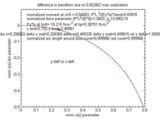
If you assume the area moment will be reduced by a factor that is equal to 1.5*ovalization then you would expect the B stiffness curve to be reduced by an equivalent amount.
Here is the bendform I get with that reduction (red curve) that overlays the shape expected with no ovalization that is plotted in the blue curve. You can see the two normalized shapes are nearly overlays of each other.
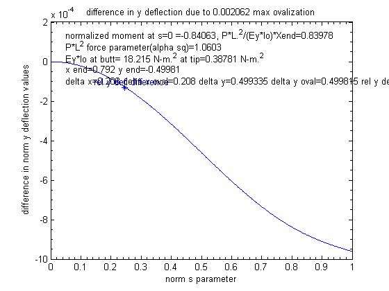
Here is a plot of the difference in the two curves that shows the impact on the tip deflection related to the ovalization factor given by the Abaqus run.
You can see the relative deflection difference related to the ovalization effect on the stiffness was around .095%. Thus the impact of the ovalization is about .02/.00095=21 times smaller than the 2% difference you saw in the deflection you predict with the Euler model vs the more complete FEM model in the professional Abaqus software.
What is involved in solving the cubic equation for the Brazier effect? It appears that solution is spot on compared to the Abaqus result. Are you still assuming the sqrt(E_t/E_l) is around 4?
Gordy
"Flyfishing: 200 years of tradition unencumbered by progress." Ralph Cutter
The input information is no secret. If you want a copy of my large deflection programme with the corresponding input, just drop me a mail adress through the ikonboard.
The pictures you can see have been drawn from my own data and the file provided by the computing center. If you want to know the details of the assumptions used by Abaqus, you can download them, but there a few hundred pages to read.
You may be skeptical about Abaqus data but I do not know on which ground you can say there are obvious anomalies. Maybe you can provide us some illustrations to explain and support your view.
Merlin
Fly rods are like women, they wont´play if they're maltreated.
Charles Ritz, A Flyfisher's Life
I would have bet you would compute something to derive the effect of "pure" ovalization.
It is somehow a surprize to me to see that the main difference in between both modeling lie in the assumption (Hi Grunde: "always question the assumptions").
Now I think I can test some glass design to see how large can be ovalization under similar conditions. It should be larger and "more visible". The assumption problem will remain, I shall never be able to introduce more precise assumptions in my own model, and I shall have to leave with the "rigid" conditions of Euler.
Merlin
Fly rods are like women, they wont´play if they're maltreated.
Charles Ritz, A Flyfisher's Life
I am still waiting for someone to tell me what a 5 wt rod IS and how is different from a 4 or 6 wt rod.
Bill,
Merlin has provided a curve that answers your question based on its measured normalized spring constant value.
Now, you are talking about fast and slow rods. How fast is a fast rod and how do you determine what it is.
I think the guidelinse that Dr. Spolek established long before CCS was invented are as good as any.
Slow rods have natural frequencies below 2.8 Hz. Fast rods have natural frequencies above 3.2 Hz, and medium rods fall in between.
If you prefer the 15 degree system based on measured tip speeds then you could use the speed factor designations established by Reim that are based on actual recovery speed measurements.
The Speed Factor
If then also the speed (m / sec) in relation to the action length (length measured from tip to top of handle), we can compare the character of rods of different lengths. The higher the speed factor, the faster the rod.
One can divide this speed factor into 3 groups. Up to Speedfactor 1.6 is slow rods. If the speed factor of 1.7 to 2.2, is a medium-speed and speed factor of over 2.2 is called fast rods. The term "Fast Rod" is herewith the first time exactly defined!
Gordy
"Flyfishing: 200 years of tradition unencumbered by progress." Ralph Cutter
Now I think I can test some glass design to see how large can be ovalization under similar conditions. It should be larger and "more visible". The assumption problem will remain
Merlin,
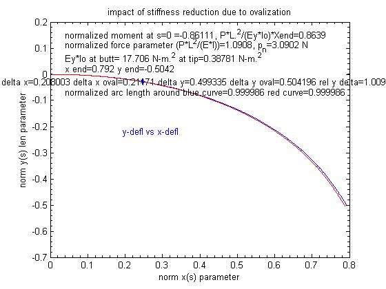
Even if the ovalization at the butt goes to 2% my simulations still predict a very small effect on the maximum y deflection (.9%) as shown below:
As you noted in the other thread I think the strain limit will cause the the blank to break before the ovalization has a big effect on the stiffness of the rod.
Gordy
"Flyfishing: 200 years of tradition unencumbered by progress." Ralph Cutter


