Hello Eugene,
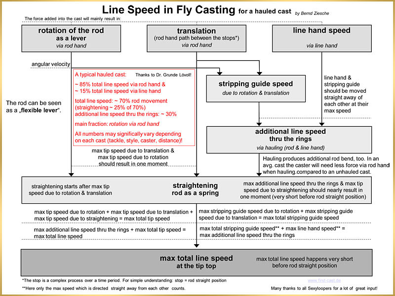
here is a sheet I put together a while ago about how I understand line speed in Fly casting by now.
Many thanks for all input I got to understand all this (slowly) better, like for example Grunde, Gordy & Merlin!
I don't think constant tip speed will be easy to achieve anyway. But for sure I have never seen any Casting Analyser chart yet showing such a cast.
Thanks Bernd,
One aspect seems to have been overlooked.
Rod deflection and it's affect on reducing the tip speed due to reduction in effective rod length.
As the rod is loaded the blank deflects reducing it's effective swept area and it's tip velocity as a function of it's distance from the rotation axis. The rotational velocity imparted by the caster is partially lost to rod deflection. This energy is restored at the rod deflection rate, not at the control of the caster.
I believe that is one of the reasons adding extra power does not always equate to longer casts. If the rod has a low spring rate all the power and tip speed is lost to deflection. The caster finishes the cast and waits for the rod to catch-up. Adding extra power adds deflection which reduces tip speed further and you end up waiting for the same results, with an excessive tailing loop for your efforts.
The goal of the cycloid is to reduce total force resulting in less rod deflection and more rod tip speed. The constant velocity allows additional time for the rod spring rate to react prior to decell. Smoother application of power over a long time frame. Reduced power required and smoother results.
Gordon,
How do you output your graphs ??
I could also send the raw spreadsheet if you would prefer and you could make the graphs and post them. You would probably do a much better looking job and I'm sure you could glean additional thoughts from the raw data.
My apologies, as an engineer, I don't normally prepare data for presentation and use by others.
Hi Tom,
the CA shows the change in angular velocity (deg/sec.)over a time period. This is what I call acceleration.
For the smoothness ratio it will set up a break point to the graph and then compare the avg. numbers for acceleration on both sides of the break point.
If it will be the same = constant accel., the smoothness ratio will we 1,0.
If someone would have constant speed over a certain time period we would see it directly in the graph.
Of course we want to achieve near constant acceleration (or at least smooth acc.) for most casts.
Hi Eugene,
my goal was to understand what we do with our line and rod hand and what are the effects which each hand brings in.
Most casters only train casting with hauling and very seldom train casting with rod hand only. I find this is interesting when seeing how many percentage of the cast is done via rod hand movement.
That is why I did not include air resistant, inertia, line angle and length of leaver to my sheet which of course all have an effect on the speed number.
I will try to get behind the cycloid stuff better!
Interesting stuff for sure!
Thanks
Bernd
How do you output your graphs ??
I could also send the raw spreadsheet if you would prefer and you could make the graphs and post them. You would probably do a much better looking job and I'm sure you could glean additional thoughts from the raw data.
Eugene,
The raw Excel data would be fine.
I can paste that directly into Mallab file, and then interpolate those sample values as needed to get the input acceleration profile used in the simulation.
the CA shows the change in angular velocity (deg/sec.)over a time period. This is what I call acceleration.
Bernd,
I think you are saying, "the local change in angular velocity with time [delta_ang_vel/delta_time] is the angular acceleration measured in deg/sec.^2;
The CA measures the angular velocity for the butt rotation in deg/sec.
The angular acceleration would need to be computed from the derivative of the measured angular velocity values and would be measured in deg/s.^2.
And does the Casting Analyzer showing the tip speed?
Tom,
Not directly since the flexible tip does not have a 1:1 relationship with the stiff rod value that would be related to v(m/s)=radius(m)*angular velocity(rad/sec). That radius will vary because of the varying distance you get from the changing rotation center and the tip of the rod.
You can use the angular acceleration that can be derived from the measure CA data and run it through the extended casting model as described here to predict what the tip speed profile would be, but you cannot get the tip speed directly from the CA data.
Gordy
"Flyfishing: 200 years of tradition unencumbered by progress." Ralph Cutter
Bernd,
The related movements should be considered as separate events with different start times in the cast duration.
Each event may have it's own displacement, duration and velocity profile all culminating with the decelleration of the rod.
Rod tip speed can then be viewed as a combined event with discreet velocity and acceleration factors.
Again the cycloid profile can be applied for each event. Since the profile starts with zero acceleration, the event start will not introduce shock to an already existing event.
Translation starts it's event and ends at a displacement, roughly linear. It requires high torque as all mass must be accelerated.
The distance traveled can be determined based on existing photographic measurements. Its also the longest time event.
Just prior to max acceleration of the translation event, the rotation event will comence. This will be a radial output of measured degrees displacement, also based on photographic data. This event will end approximately the same time as the translation. This will be a high velocity, low torque event based on the effective rod length from the axis of rotation and the inertia of the rod and aerialized mass. Assuming the rod has been deflected by the translation event and the effective radius reduced torque will be lower allowing higher velocities.
The sum of the events may be interpretted and viewed as a combined event at the rod hand interface.
The percentages of acceleration, constant velocity and harmonic may be adjusted to better work with the spring rate of the rod. This will be accomplished by reducing cycloidal event time and increasing constant velocity time to find the "sweet spot". Since the constant velocity portion has no acceleration the rod spring rate will be returning stored energy. As this energy is released the effective rod length will increase providing additional velocity to the rod tip and line.
The haul will be an additional short term event that will begin and end within the stroke timing. We can examine photos to determine timing start and stop with linear displacement of the line.
Gentlemen,
I've a grocery list that you might make me more knowledge on.
I need some information about competition level casting.
Event Grocery list
Translation event
Horizontal travel distance linear
Vertical travel distance linear
Time duration seconds
Rotation travel event
Rotation displacement degrees
Rotation finish angle from vertical
Rotation time duration
Relative start time
Rotation caused by translation ???
Haul event
Haul displacement travel linear
Haul displacement relative start time
Haul displacement time duration
Relative timing chart
Start translation
Start Haul
End Haul
Start rotation
End rotation
End translation
Components from single cast event
Based on cast performance or loop shape
Best components from multiple casters ( The Great One )
Rod specification ( MOI, deflection characteristics )
Line specification
Line carry length and weight@length
Calculated Results
Combine output to view rod tip displacement and accelerations ( no rod deflection )
Rod deflection based on rod load imparted from caster ( MOI, spring rate of rod at loads )
Torque requirements for rod acceleration
Rod deflection based on load normal to rod tip from line acceleration @ line carry weight
Torque requirements for line acceleration
Combined cast dynamic deflection ???
Combined cast torque requirements ???
I made a test a cannot find a significant difference between a linear and a non linear acceleration. Let's summarize it: the cast is made for a given spaceframe and timeframe. The casting arc is about 110 degrees and the timing 0.38 s (short).
The max rotation speed is above 700 deg/s for the non linear case, and 500 deg/s for the linear case. Both give the same order of magnitude for the max tip speed (some 29.3 m/s). I can send you the details.
If you impose the same arc and timing for the acceleration only, and the same overall timing, then the non linear case is better. It corresponds to a larger global arc in that case (shorter arc for the linear case).
Merlin
Fly rods are like women, they wont´play if they're maltreated.
Charles Ritz, A Flyfisher's Life
I made a test a cannot find a significant difference between a linear and a non linear acceleration.
Merlin,
I have found the same thing for Eugene's sinusoidally varying acceleration function. There is a big difference in the spring speed it produces, but that loss is compensated for with a higher continued swing speed as the rod unbends.
I will write something up to show the differences I found sometime next week.
This was a bit of an eye opener, as it shows that at least from the standpoint of line speed the exact way the rod is rotated is not very critical. You have to apply much higher peak torques for the sinusoidal acceleration case (similar to what you found for the peak angular velocity differences) but if you can then it is possible to get very similar line speeds.
Gordy
"Flyfishing: 200 years of tradition unencumbered by progress." Ralph Cutter
The acceleration profile one gets is the result of a combination of rotations (shoulder, if any, elbow and wrist). This cannot be anything, our joint motions are more or less sinusoidal. It ends up in progressive acceleration usually, the linear one being maybe an exception (difficult to control).
Now the question is, if speed are similar, what is the profile needing minimal torque?
Merlin
Fly rods are like women, they wont´play if they're maltreated.
Charles Ritz, A Flyfisher's Life
Merlin,
The minimum torque will be that of the constant acceleration.
The problem of the constant acceleration is of the shock produced on the blank as it's a flexible body. The profile will work but the energy release needs to timed with the shock wave speed and duration. The harder the shock the more critical the timing as the wave travels faster.
The cycloid creates no shock. The wave form is through acceleration only, therefore the release timing is less critical as it's a natural function of the deceleration.
I assume the values of 110 degrees at .38 seconds are for the rotation event only ??? This equates to a rotation velocity of 470 degrees per second. With a peak acceleration of 2800 degrees per sec^2.
Based on a non-flexible length this is a tip speed of 24.6 meters per second.
The objective of the proposed curve was to minimize deflection and eliminate shock to provide a deflection over time to lengthen the wave and maintain the effective rod length.
To reduce torque without shock the cycloid time may be increased by reducing the length of the constant velocity and deceleration.
The total length of the constant velocity and deceleration should be matched to the rod frequency to maximize the event.
You puzzle me. A shock for a constant acceleration? On a camshaft maybe, not here: there is no “pulse” generated by the caster. Any opinion, Grunde? I wait for Gordy’s work since I may not understand what you are describing.
I started modeling fly casting with sinusoidal forms for both acceleration and deceleration. When Noel and Bruce published their work in FFM by the end of 2003, I then tested a constant acceleration and constant deceleration. I realized it could match were well the data corresponding to the sinusoidal forms. Since I used exact mathematical solutions in both cases, using linear forms helped me to simplify the model and make it flexible to parameters. Now it just helps modeling, and I use several models, including numerical ones or a sophisticated one describing joints rotations and translation (sinusoidal forms this time).
In reality, we do not perform real constant acceleration, and I cannot tell if our joint rotations are close to cycloid forms or not, but anyway I do not think we can control our motions so precisely. We use elbow and wrist rotation to adapt our casts to fishing conditions, without thinking about their mathematical form. Sometimes we use more wrist, sometimes more elbow, it just depends on the conditions.
PS: 110 degrees and 0.38s are the total rotation angle and total duration time. I retuned the parameters for lower load and get speeds about 37 to 38.7 m/s (advantage for the non linear form).
Merlin
Fly rods are like women, they wont´play if they're maltreated.
Charles Ritz, A Flyfisher's Life
Merlin,
I believe we are quite capable of producing shock in a spring driven system. The fact that we can feel and adjust would suggest that we are aware of the action and are compensating to eliminate it.
Like you I believe we are not capable of constant acceleration over a long range of body motion. Even a short one is questionable.
The spreadsheet I sent to Gordon uses a geometric curve shape that is utilized on high-speed cams. I believe it represents a velocity profile that is humanly possible and exhibits no shock load.
The constant acceleration is used in several cam profiles, but is always preceeded by a cycloid to eliminate shock. This may be a portion of the adjustment that we can physically make in our cast.
I don't think the rod is capable of sustaining how quickly we can apply torque. The cycloid applies this torque slowly allowing the rod to accept the load in one long continuous deflection. (Assuming we are capable of that). The reduction in acceleration over time allows some of this energy to be returned while we continue to accelerate. How much and how quickly depends on the rods spring rate and the amount of line carried.
Do you have an acceleration profile for that case? I should be able to simulate the expected response for any acceleration vs time curve.
Eugene,
Thank you for sending me the acceleration and deceleration curves you have been referring to as “cycloid” acceleration. The curves you sent had a half period sine wave response for the acceleration portion and a quarter period for the deceleration value so it was easy to scale them to match up with the car velocity values Grunde used in his car/spring/brick model.
To compare that acceleration with a known case I scaled the amplitude and frequency of the sine wave response to give the same swing velocity as Grunde measured for the Paradigm cast. The curves for that cast have been shown many times in the past, but I will repeat them here so it will be easier to compare those constant acceleration curves with yours.
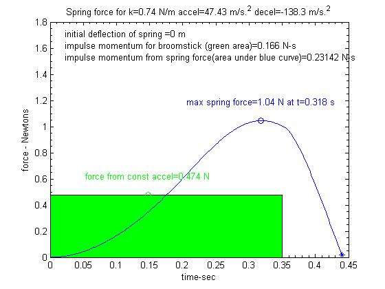
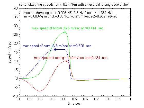
The input parameters to the model in this cast were a constant acceleration of 47.4 m/s.^2 for .35 seconds and then a constant deceleration rate of -138.3 m/s.^2 to stop rod in the .35<t<.47 sec time interval. The peak velocity produced by this acceleration rate was 16.6 m/s. The rod parameters were m0=.003 kg, m_brick=.007 kg, k=.74 N/m. In an attempt to take the non-linear spring constant of the rod into account the force vs deflection curve was assumed to vary as f_n= .74(x +.3*x.^3) For small deflections this gave an unloaded oscillation frequency of 2.5 Hz, and a loaded frequency of 1.37 Hz.
Here is the force vs time curve that was expected for that cast. This shows the lag in the force from the start of the applied acceleration to the maximum deflection force produced by the rod deflection. That lag is nominally equal to one half period of the loaded oscillations frequency of 1.37 Hz or .5/1.37=.365 seconds.
You can see that the peak force applied to the line from the deflection in the spring was 1.0 N. The corresponding force that would be applied to just the mass of the line from the constant acceleration of the butt would be f=ma or f=.01*47.4 [.47 N]. The peak force from the spring (1.0 N) is more than twice the “broomstick” value (.47 N) because of the non-linear k value. In addition to having a larger amplitude the positive force from the deflection in the spring was applied over a longer time. That resulted in the force impulse (the area under the blue curve above) from the spring deflection was .23N-s compared to only .16N-s from just the acceleration factor alone.
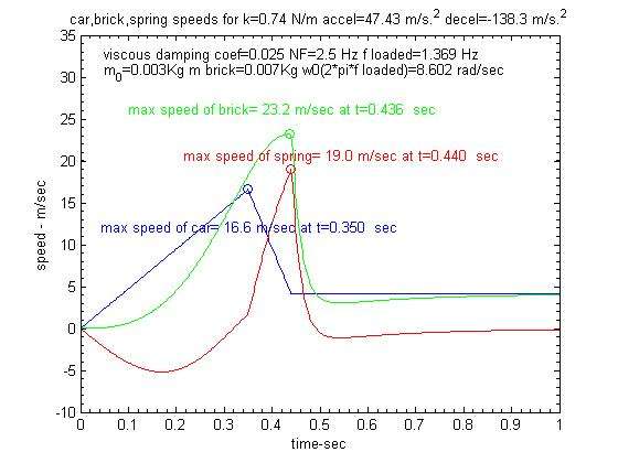
The force impulse determines the change in the momentum of the brick. Since it has zero initial velocity the force impulse would be expected to increase its velocity to .23/.010 or 23 m/s. You can see that matches up with predicted velocity of the brick for this set of parameters as shown here.
This model assumes the line velocity will equal the sum of the spring velocity plus the swing velocity at each point in time. You can see the spring velocity for this case when the spring deflection was zero (equivalent to RSP) was 19 m/s and the swing velocity from the continuing rotation of the rod was only 4 m/s. We will see this ratio was much different for the sinusoidal acceleration function followed by a relative long application of constant rotational velocity of the butt.
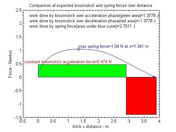
The force applied over distance curve for this cast is shown below:
This shows the work energy applied to the line by the rod (2.76 J) was about twice a big as you would expect for a broomstick rod. This work energy will determine the kinetic energy applied to the line so the expected velocity would be 1/2*m*v.^2=2.76 or the max velocity would be equal to sqrt(2.76*2/.010) or 23.5 m/s which does match up with the peak velocity of the brick as shown above.
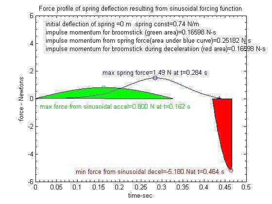
Here is the force vs. time curve found by applying your scaled sinusoidal acceleration function in the model.
Just as with the “shock” applied to the rod with the step in the constant acceleration case there is still a sizable delay in between when the maximum acceleration is applied (t=.162 s) to the butt of the rod rod and when the lag in the spring reaches its maximum deflection point at t=.284 seconds. Also since the acceleration starts to decrease before the max deflection point is reached the maximum force from the spring (1.49 n) is less than twice the value expected for a broomstick (.8 N).
Because of the long section of constant velocity that links the sinusoidal acceleration curve to the sinusoidal deceleration curve the spring velocity (10 m/s) is smaller than the swing velocity (16.6 m/s) at the point of maximum line velocity as shown below:
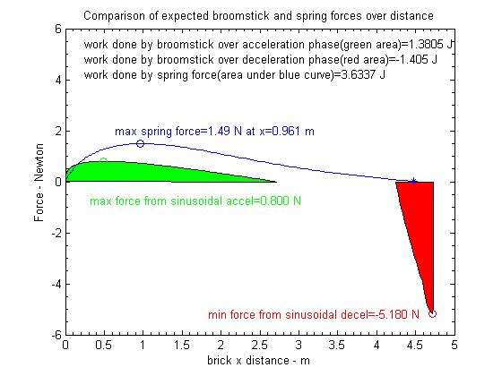
The force applied over the distance the rod tip travels while the force from the spring is applied to the line is shown below:
This shows that the distance the rod tip moves during the constant velocity portion of your forcing function (the gap region between green and red acceleration blocks) contributes a significant amount of work energy as the deflection in the spring goes back to zero at the t=4.6 meter point. Thus it is the added distance the tip is moved with the sinusoidal and constant velocity times (4.6 m) that ends up producing a slightly higher line velocity than the constant acceleration case where the tip travel distance was only 3.7 m.
Since the MOI of the rod and line was the same in both cases, the peak torque required to implement the same swing velocity value was quite a bit higher for the sinusoidal acceleration case (80 m/s.^2) versus the 47 m/s.^2 constant acceleration value. In addition to requiring higher torques, I don’t know how well a human could produce such a ramp up, ramp down, constant velocity followed by a rapid deceleration time required for the more complicated sinusoidal forcing function.
It would be interesting to program Noel’s casting robot to get this type of forcing function and see what it would do the shape of the loop.
However, from a speed standpoint it appears the velocity out is related to energy applied at the butt, therefore the ultimate line speed is not a sensitive function of the actual shape of the acceleration function applied to the butt. That is with the caveat that the acceleration function used would fit within a reasonable casting arc.
Gordy
"Flyfishing: 200 years of tradition unencumbered by progress." Ralph Cutter
However, from a speed standpoint it appears the velocity out is related to energy applied at the butt, therefore the ultimate line speed is not a sensitive function of the actual shape of the acceleration function applied to the butt.
This simple sentence is just fundamental. Although I model the total energy input differently (rod swing weight under rotation instead of equivalent mass mo at line speed, drag losses included), my conclusion is the same: the max tip speed is proportional to the energy input. That input depends on the caster’s motion (force, torque), and on the reluctance of the rod to move (inertia, elasticity). This can be summarized by its loaded frequency. I did a few checks and it works.
I don’t know how well a human could produce such a ramp up, ramp down, constant velocity followed by a rapid deceleration time required for the more complicated sinusoidal forcing function.
In fact, our joints produce nearly symmetrical sinusoidal motions (that can be found in biomechanics publications), and not cycloid ones with a constant speed sequence. The last part (final deceleration) corresponds to the end of wrist rotation. So in general, we cast with a two accelerations profile (one from the elbow, one from the wrist).
Merlin
Fly rods are like women, they wont´play if they're maltreated.
Charles Ritz, A Flyfisher's Life