mo is a strange characteristic in fact.
This thread is intended to shed some light on what the effective mass (m0) is all about with the goal of making it a bit less "strange."
In coming up with the effective spring constant (K0) and effective mass (m0) values that are used in the frequency vs added tip mass equation you find that K0 is not equal to the measured spring constant value of the rod (for small deflections) and that m0 is much smaller than the mass of the rod. It is not surprising that mapping the two dimensional vibration characteristics of a long tapered fly rod would be different than the values found for the “equivalent” one dimensional model, but I have always thought there should be some way to convert the true mass of a blank to the equivalent m0 value used in Grunde’s and Merlin’s model of the cast.
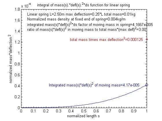
What is the physical significant of the effective mass term? The best description is given in this MIT lecture on the subject by Dr. Lewin at M.I.T. He explains how the added m0 term can be used in a mass/spring oscillator model to account for the kinetic energy that is associated with the mass in a real spring at about 32:00 in that video.
Here is the excerpt from French’s book that he mentions in his lecture.

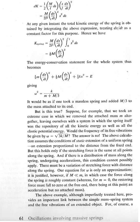

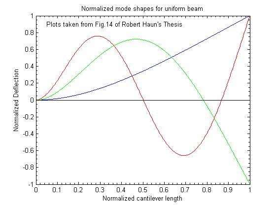
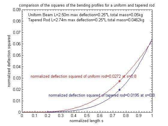
The relative displacement in a cantilevered beam is not a linear function of the length as is in a spring so the energy analysis for the mass in an oscillating fly rod is much more complicated than the procedure described above for a spring.
Merlin found a method that can be used to estimate the divisor for a stiff cantilevered beam that can be used as a starting point for a fly rod. We both had some dimensioning errors where this was discussed in another thread, so I hope that these equations will be more accurate.
To simplify this analysis I will express the frequency in terms of its radians/per second (omega) counterpart. The equivalent frequency can be determined by f=omega/(2.*pi).
The (omega frequency).^2 of the first mode for a vibrating beam is equal to
Omega.^2=(1.875^4)*EI/(L.^4*rho*Ao) (1)
where:
E is the Young’s modulus in N/m.^2
I is the area moment at the butt in m.^4
L is the length of the cantilever in m
Rho is the mass density in kg/m.^2
Ao is the area at the clamped end of the rod.
The total mass of a uniform beam is just rho*A*L so as Merlin pointed out equation (1) can be re-written as:
Omega^2=1.875.^4*EI/(L.^3*m_rod). (2)
The (omega)^2 of a spring/mass SHO is equal to:
Omega^2=k/m0 (3)
Where:
k is the effective spring constant in N/m.
m0 is the effective mass in kg
Given that the deflection at the end of a uniform stiff beam for a tip load of N Newtons is:
deflection=N*L.^3/(3*E*I) meter gives a corresponding k factor of
k=3*E*I/L.^3 N/m. (4)
Substituting that value into eqn (3) and setting the result to the same omega.^2 value in eqn(2) we find:
3*E*I/(L^3*m0)=1.875.^4*E*I/(L^3*m_rod) (5)
Cancelling terms you find:
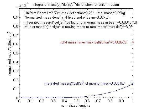
m_rod/m0=1.875^4/3=4.11
Thus as Merlin noted in the other thread the divisor used to convert the mass in a stiff, uniform, cantilevered beam to the m0 value is around 4.
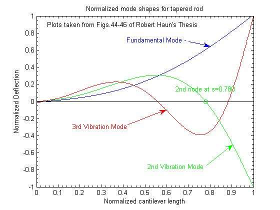
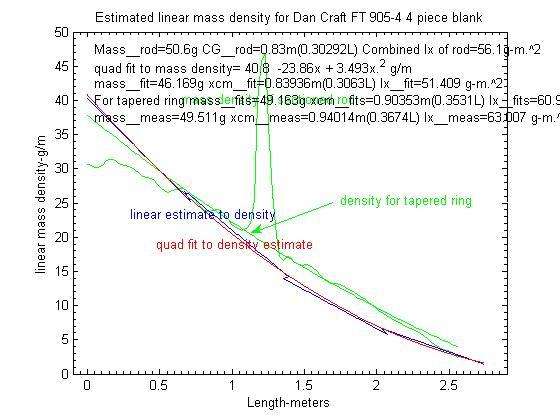
For one of my saltwater blanks I have found that m_rod/m0 ratio was equal to 11.8. Thus the equations for the uniform beam are going to have to be modified to get a value that makes sense for a tapered rod.
My thanks to Merlin for correcting my other derivation that ended up with an incorrect additional L term regarding the ratio of m_rod/m0. I think we now agree on how this is derived and can use this as a starting point to get a reasonable value for a flexible fly rod.
Gordy