I think I will start a new tread addressing the total forcing torque in the cast to address Server Sadik's claim that the caster does not exert retarding moments to stop the rotation of the rod.
This thread will investigate if the claim made by Server Sadik (that many people seemed to agree with in the harmonic oscillator thread ) :
"Fortunately, it can be easily shown that prior to RSP the caster never exerts retarding moments//torques on the rod and this fact is intuitively consistent with everything most people would believe about fly rod behavior during casting."
can be supported (or refuted) by straightforward rotational dynamics principles.
The concepts used in rotational dynamics are not as well known at those in translational dynamics so some readers may want to refer to some resources on the web to get a better understanding of how the work and energy concepts in those two frameworks are related to each other. That background will make it easier to understand the analysis that Merlin and I will be doing to answer this intriguing question.
Energy Consideration
Before I jump into the analysis, it may be worthwhile to address the “intuitively consistent” assumption in Server Sadik’s rather surprising statement. My intuition would say that in order to stop the high angular momentum of the rod at MAV it would be necessary to apply some reversing torque to the butt of the rod. That torque would then produce the force impulse or negative work energy required to halt the rotation of the rod.
Thus (as Merlin has repeatedly pointed out) in order for the P.E. in the rod to supply the reversing torque all by itself; it would be necessary for the P.E. in the rod at MAV to equal to (or exceed) the rod’s K.E. at MAV in order for the unloading of the rod to completely stop (or reverse) the rotation.
gordonjudd wrote:I think that some analysis will show we do "put on the brakes" as Merlin characterizes it. As noted in post #144 I disagree with Grunde and Walter that the rod will unload as fast as it does since the potential energy in the rod is so much smaller than its K.E. at MAV, but time (and a new torque analysis routine) will tell.
followed by Grunde's response Sorry I do not understand these statements...
Grunde, maybe some computed values will make it easier to understand the point I was trying to make about relative energy values.
As described in the Wikipedia article the K.E. of a rotating body is given by ½*MOI*(angular velocity)^2.
In the Paradigm cast the combined MOI of the rod and reel taken about the elbow( the elbow was near the center of rotation at MAV in that cast) was .14 kg-m^2 and the angular velocity of the rod at MAV was 6.6 rad/sec.
Note: Everyone might not be familiar with the radian measurements that must be used for the phase values when performing rotational dynamics calculations. There are 2*pi radians in a circle so 1 radian=57.3 degrees.
Those values would result in a K.E. of .5*MOI*ang_vel.^2 =.5*.14*6.6^2= 3.0 J.
Similarly the P.E. in a spring is given by ½*k*x^2 where k is the spring constant and x is the deflection in the spring. For the Paradigm cast the maximum deflection was 1.26 m and the rod’s spring constant was .74 N/m. Thus the P.E. in the rod at MAV would equal .5*k*x^2 or .5*.74*1.26^2 =.59 J.
Thus just based on energy values, you can see the P.E. in the rod would not be sufficient to stop the K.E. in the rod all by itself. Consequently you would expect that an additional energy source would be needed to stop the rotation of the rod over the short time range we see from MAV to RSP in classic casting styles.
Unloading Time
The loaded frequency of the rod/line for the Paradigm cast was 1.2 Hz. As discussed here if the caster did not put on the brakes to stop the acceleration of the rod rotation then the time for the rod to unload by itself would be .5/1.2=.417 sec.
However, Grunde’s measurements found the actual unloading time was .122 second. Thus to get the fast stopping time we see in casting you would expect that some additional reversing torque must be applied to stop the rod more quickly.
Reversing Torque Sources
That additional reversing torque most likely comes from a combination of the joints that are used to rotate the rod in casting depending on the caster’s style. For Chris Korich, the main source is from the elbow, for others it might come from the wrist.
Determining which joint is providing the maximum reversing torque is complicated, but could be inferred by looking at the moments produced by or acting upon each joint. That could get a bit messy, so I will just be looking at those values about a single point (the elbow) in this analysis. That approach will no doubt be complicated enough for most readers of this thread.
Expert Opinion
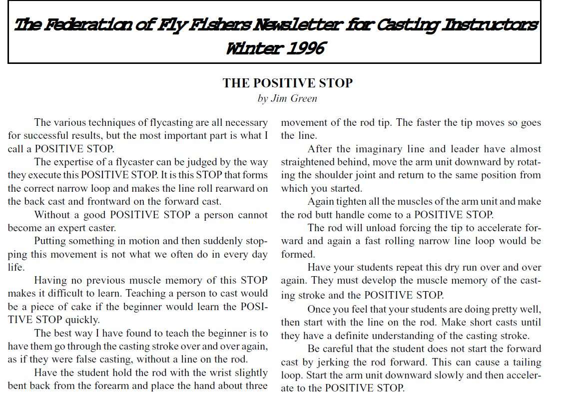
If these values are not convincing to you, then take a look at what Jim Green said about the importance of the positive stop in casting that was given in a “Loop” article several years ago.
I don’t know how many times “positive stop” is used in this article, but after reading it I think you will agree that Mr. Green felt that applying some reversing torque by “tightening the muscles of the shoulder, biceps, forearm, wrist, and hand.” is a key element of casting.
Casting Analyzer Measurements
The point Jim Green makes in this article that the rod will tend to bend automatically, but requires a positive stop input from the caster to get it to unload over a short rotation distance was born out at a clinic that was conducted at the Long Beach Casting Club several years ago.
At that clinic, Noel Perkins and Bruce Richards used their newly developed CA to show people the key elements of their casting stroke using a single rod that was outfitted with the analyzer. The thing that was very apparent from those measurements was how similar the MAV values were from caster to caster; and yet how different the corresponding deceleration values were. Interestingly, they found that the better casters in the club produced much higher deceleration values when they stopped the rod.
If the rod was able to quickly unload by itself, you would expect that the stopping times and deceleration values for different casters would have been similar since everyone was using the same rod. That was not the case, and indicates that good casters do exert significant retarding moments to stop the rotation of the rod.
How big that reversing torque happens to be will be investigated in later posts, but I think this is more than enough for now to start a discussion on this interesting subject.
Gordy
"Flyfishing: 200 years of tradition unencumbered by progress." Ralph Cutter
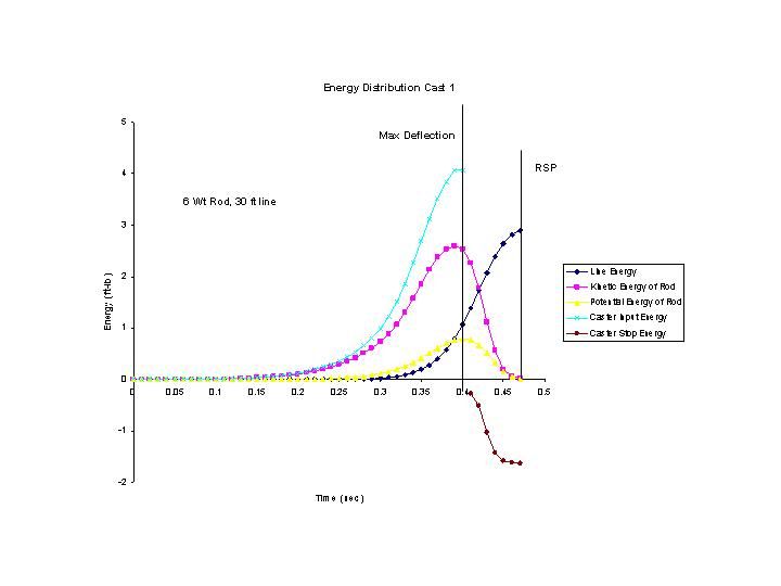
My data says Gordie is right. Below is a plot of a cast on my model with a 6 wt rod, 5 oz. reel, 30 ft of line.
The cast energy is CUMULATIVE energy. The other energies are kinetic and potential. You can see the torque is reversed at max rod deflection causing a reverse energy input to the system. The amount of breaking energy is less that the total kinetic energy in the rod. The other portion of that energy goes into the line as well as does the potential energy in the rod.
This model is not without caviats and may have some logical errors still lurking in the shadows but it shows two things:
It shows a reasonable energy flow.
It shows rod motion can be calculating with nothing more than Newton's laws and the equations of motion. There is no frequency calculation anywhere in this model.
I will start a separate thread to show the details when I get it cleaned up. This is just to whet your appitite.
but I think this is more than enough for now to start a discussion on this interesting subject.
Wrong again! The silence so far about such an important concept is deafening.
Maybe this topic is too obscure or general to stimulate any questions. But I know if someone told me the caster does not apply any negative torque to stop the rod, I would ask them how that is even remotely possible. I know I make a conscious pull back to stop the rod as quickly as possible in my own accuracy casting, and see something similar in tournament casters who are much, much better casters than I am. Consequently, I have always agreed with Jim Green’s conclusion that:
A positive stop is the secret to Flycasting!
This would seem to be a very fundamental question about the physics of casting, so I think it is worthwhile to do some straightforward analysis to answer it. Do we exert retarding moments/torques on the rod to stop its rotation from MAV to RSP or not? Let’s look at a simple model to compute some relevant torque curves and see how it works out.
I think part of the confusion about the torque relationships made in the harmonic oscillator thread have to do with separating out the differences between the forcing torque produced about some rotation axis, and the resulting reaction moments to the bending in the rod that appear at some other point on the rotating body. Thus I think it will be useful to separate out those two factors and make it easier to see what is going on.
With that in mind, I will start with a simple model based on the operation of the casting robot Noel Perkins developed. The mechanics of the robot makes it easy to see a clear delineation between the driving torque produced by the stepper motor and the reaction moments provided by the straps they used to attach the butt of the rod to the stepper.
Here is a picture of the robot that was constructed with a single rotation axis that was then attached via a rigid linkage to the butt of the rod as shown in the picture below:
The stepper motor used in the robot had enough reserve power to maintain a given angular rotation rate regardless of the MOI that was attached to its rotation axis. Thus if you programed the stepper to produce a measured angular velocity curve then a CA attached to the butt of the rod would follow that curve with a high degree of precision. The torque the stepper motor used to produce that angular velocity profile would vary depending on the magnitude of its load. However, if you could measure the power it used to replicate the specified angular velocity profile , then you could calculate the varying driving torque it produced to make a cast.
From this picture you can see the bending moment produced by bent rod was resolved with the force couple provided by the straps clamping the butt of the rod to the rotating linkage. This represents the ultimate “stiff wrist” caster.
You can infer that a strain gauge attached to the butt of the blank would be able to measure that bending moment produced by the bend in the rod, but it would be totally blind to the forcing torque that was being produced by the stepper motor. Only the power consumption of the motor would provide a measure of the total forcing torque. I hope you can see the difference in those two torques, and how they could be measured. That is the source of the confusion about what torques are applied to stop the rod, and how they might be measured.
The power providing the torque to the stepper motor would be proportional to the total forcing torque, but would have no relevance to measuring the bending torque in the rod. The reverse of that relationship would hold for the strain gauge.
I think the total torque the stepper motor needs to produce during the cast has two main components. 1. Torque #1=MOi(rod and reel)*angular acceleration component.
That MOI value will change a little bit with the rod deflection but since we are primarily interested in what is going on right at MAV , I will just use the combined MOI value at that point and assume it has that constant value throughout the cast.
2. A force x radius (cross product) component coming from the acceleration force applied to the line.
The f , r, and angle required for that calculation and will vary during the cast, but I think we can make some reasonable assumptions on the tip path to find that the (x r) component will have a nominally constant value for a circular tip path about the rotation axis.. Thus we can use a constant (x r) value that is equal to the perpendicular moment arm distance of the bent rod we see about the elbow in the Paradigm cast at MAV.
The force component in that equation can be derived from the kx factor we see for the varying x deflection in the spring from the car/spring/brick model
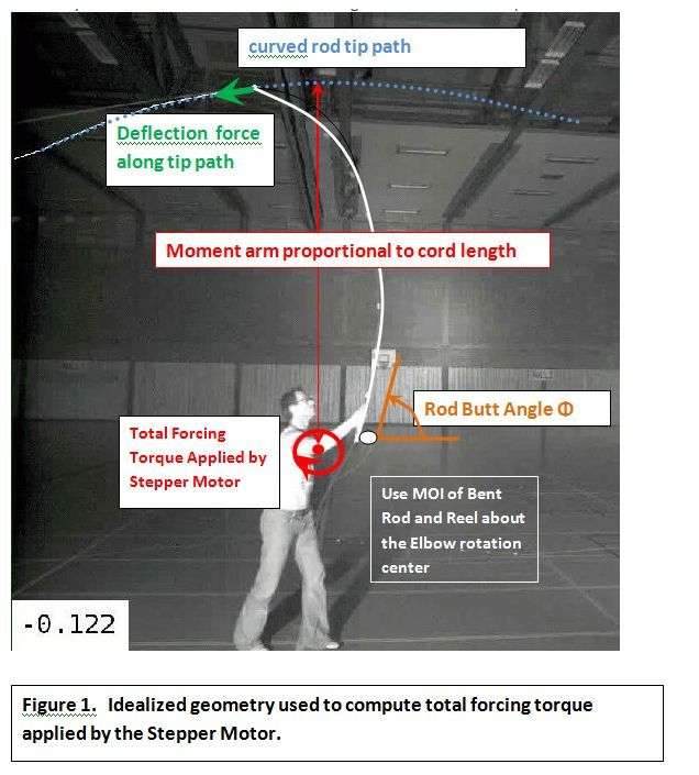
Here is the geometry that will be used in this analysis.
Thus all that we need to calculate the total torque being produced by the stepper motor is to assume that:
MOI*ang accel=Tstepper +(f x r) or
Tstepper=MOI*ang_accel- (f x r).
I.e. the torque from the stepper motor is equal to the torque required to accelerate the MOI of the rod and reel minus the torque that results from the f X r moment from the acceleration force on the line. To get the proper total magnitude of the forcing torque produced by the stepper motor, it is important to take the direction of the two torques into account.
Using the right hand rule to get the direction of the torques you can see the direction of MOI*ang_accel term will be towards the –Z axis when the rod is being accelerated clockwise and towards the +Z axis when negative acceleration is applied. The (f x r) vector will always be directed along the +Z axis.
From the signs of the moments involved you can see the torque produced by the stepper motor will be equal to the sum of the absolute torque magnitudes up to MAV and then will equal the difference of the magnitudes when the negative acceleration is applied.
I will ignore the added MOI of the linkage used to connect the rotating axis of the stepper to the line in all of this, as the net work energy used to drive that linkage will be zero and we are just interested in the torque required to rotate the rod and reel.
The same is true for the potential energy in the rod. It will not have any positive net work effects during the cast, but would require some additional torque to load the rod and then reduce the torque required going from MAV to RSP.
I could not work out the work energy required from a torque over angle standpoint to include the rod P.E. effect, but since it is relatively small compared to other energy components in the cast I don’t it would have much of an effect on the results. Merlin will be using a rod P.E. component in his energy approach to this problem, along with an additional K.E. associated with the effective mass (m0) and spring velocity in the rod, so it will be interesting to see how much difference those two energy components make to the total forcing torque.
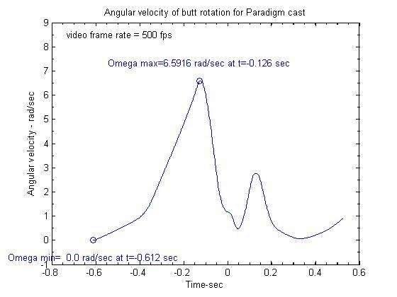
Here is the velocity profile that would have been followed by the stepper to emulate the Paradigm cast.
Taking the derivative of that curve you get the angular acceleration curve that is needed in Grunde’s model.
Using the measured spring constant (.747 N/m) and effective mass (mo=.0031 kg) for the Paradigm rod results in this deflection profile from Grunde’s model.
That produced these speed values:
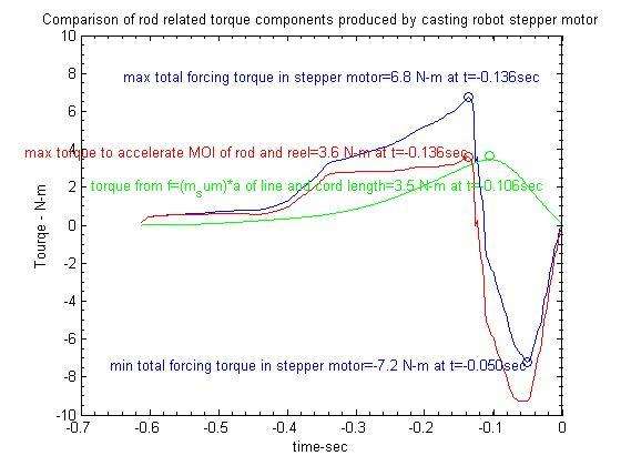
With the above data it is a simple matter to get the different torque components as describe earlier. The cord length of the bend rod used to get the moment from the f x r required to accelerate the line was 2.5 m. That radius is also used to transform the translation values to rotational values, and vice versa,
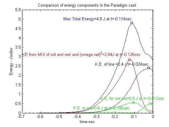
And finally here are the relevant energy values:
So do we exert a negative torque to stop the rod.? The blue curve for the total forcing torque produced by the stepper motor would argue that we do. In fact it reached a peak value of around -7.2 N=m in the Paradigm cast. If you wanted to stop the rotation of the rod even quicker, then even more deceleration would have been required, and that would required an even larger negative torque as compared to the one shown above.
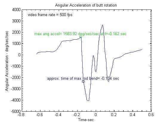
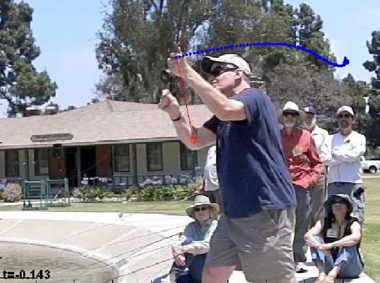
For instance as shown below the deceleration rate Mathias applied to stop the rod in this cast was around -4000 deg/s^2.
Noel measured the deceleration rate that Tim Rajeff applied in one of his casts to be -7400 deg/s^2. That means the negative torque Tim applied to stop his rod was about 7400/4000=1.8 times more than the negative torque Mathias used in the Paradigm cast.
Now it will be interesting to see what Merlin gets using a more sophisticated model that does includes the P.E. and K.E. components in the rod.
Gordy
"Flyfishing: 200 years of tradition unencumbered by progress." Ralph Cutter
Bob,
Good to see that your model is working out. It appears we are getting similar curves and if you multiply your lbf-ft values by 1.35 to convert to Joules, we have similar peak energy values as well.
The main difference appears to be in the energy profile for the line. In your plot it appears to be 1.5 J at MAV and 3.9 J at RSP1. Grunde's model gives an energy value of 1.6 J at MAV and 2.4 J at RSP1. In fishing casts the line speed at MAV is around 75% percent of the maximum velocity. Thus the energy ratio would be around 55%. Your values appear to be 38%, while Grunde's model gave 66% for the Paradigm rod. To get something around 40% would take a very soft rod which may explain why your rod P.E. appears to be around 1 J, while it was only .6 J for the Paradigm rod.
What were the peak deflection and spring constant values for your rod? What did you used for rod butt acceleration and deceleration values?
This is a nit, as I don't know how much of the P.E. in the rod is actually converted to K.E. in the line, but there will be an additional K.E. component in the rod that is due to the moving mass in the upper section of the rod about the "broomstick" reference that comes from the rotating shadow beam.
Merlin and I just assume that component can be inferred by taking 1/2*mo*(spring velocity).^2 as laid out in this thread.
You can see that K.E. component is a maximum at RSP1 and is nominally equal to the max P.E. value. That implies that most of the P.E. in the rod is just converted to K.E. in the rod as its unloads. That is the energy that must be damped by the caster as the rod goes through counterflex as Grunde mentions here
I doubt that internal energy conservation condition is always the case, but it indicates that the P.E. in the rod does not make much of a contribution to the K.E. of the line. Rather, just as it does in a SHO most of the P.E. in the rod just gets converted to K.E. in the moving tip deflections.
Well done! The more models we have, the better. I will be interested to see how you are doing this, and will look forward to reading your new thread.
Gordy
"Flyfishing: 200 years of tradition unencumbered by progress." Ralph Cutter
gordonjudd wrote:Maybe this topic is too obscure or general to stimulate any questions. But I know if someone told me the caster does not apply any negative torque to stop the rod, I would ask them how that is even remotely possible. I know I make a conscious pull back to stop the rod as quickly as possible in my own casting, and see something similar in tournament casters who are much better than me. Consequently, I have always agreed with Jim Green’s conclusion that:
A positive stop is the secret to Flycasting!
This would seem to be a very fundamental question about the physics of casting, so I think it is worthwhile to do some straightforward analysis to answer it. Do we exert retarding moments/torques on the rod to stop its rotation from MAV to RSP or not? Let’s look at a simple model to compute some relevant torque curves and see how it works out.
Hi Gordy
To assist me enormously could you please explain if these thoughts have any significance to this topic.
I regularly cast a 44gram 54ft floating shooting head on my 10# single hander, I visualise the head as like a ball on string of which I am going to sling away with the tip of the rod, Ideally I want to throw it high and release early.
When i am accelerating the head during the forward cast, the initial weight take up at line straight "which i call the tension jolt, a time which has caused the most casting injuries in the past", feels like it gets lighter as it begins to move, I understand it cant change its mass, however eventually I can pass back this initial slow heavy load from through the torso, shoulder, arm, wrist and finally now its moving fast, into the hand and fingers.
Once the weight of the head is off the hand, all i am left with is about 3 and a bit ounces of rod, which was straightening/unloading as I was turning it, and feels very simple/easy to decelerate compared to the effort expended in casting the head..
I want to throw it high and release early.
and
Once the weight of the head is off the hand,
Lee,
Your case will have more torque coming from the f x r component associated with the head so the torque associated that component will be roughly 4.4 times larger than my example using a line mass of 10 grams.
It would depend on the acceleration you used (it could well be larger than the 10 meter cast with the Paradigm rod) so the torque required to rotate the rod and reel would also be larger. Thus we would need more data to see how those two torque values compared.
What is the rod deflection when you say the weight of the head is off the hand? If it is after the line is launched at RSP then the rotation of the rod would have been stopped prior to having the mass of the line being out of the picture.
Thus it is likely you have applied some negative acceleration to stop the rod prior to the launch of the head. Some CA data would show what is really going on.
I would be surprised if the head would go ahead of the rod prior to RSP, but some video could prove me wrong. Human reaction times are around 200 ms for a visual stimulus and 220-250 to touch. If you assume half that time for a signal to get from the hand to the brain that is just about equal to the time it takes for the rod to unload. Thus I don't know how accurate a "feel in the hand" would be in sorting out the exact time the mass of the head becomes uncoupled from the rod. It is time for one of your great videos to decide the issue.
eventually I can pass back this initial slow heavy load from through the torso, shoulder, arm, wrist and finally now its moving fast, into the hand and fingers.
It may seem like that, but from the few rotation center plots I have made the rotation center is generally near the elbow, not the wrist at MAV. That is a style issue of course but just based on the strength of the elbow vs the wrist I would expect the elbow is the biggest rotation source at MAV.
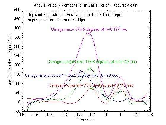
Here is where it was for Chris Korich using a shooting head.
You can see the rotation center is closer to the elbow than it is to the wrist. His shoulder, elbow, and wrist are not all rotating in the same plane in this cast, so I cannot see where the angular velocities are coming from as you could see in his accuracy cast that is shown here:
You can see most the angular velocity at MAV in that cast came from the elbow rotation, as compared to the value for the wrist. Chris is big on using the large muscles in the shoulder and elbow in his accuracy casting so he does not fatigue his wrist when false casting for a long time in the dry fly game.
Gordy
"Flyfishing: 200 years of tradition unencumbered by progress." Ralph Cutter
I need to re capture and hold all the weight on the wrist to control the line at reversal and i also need to rotate the rod about the wrist to give me my longest tip path on the delivery... I simply cant withstand the shock load and make a successful cast without moving my body etc first..
I feel the load shifts away to a comfortable level before the rod has straightend completely, on video I may be wrong..
Lee,
Yes, although it is best to do it from a high speed video taken close the caster's line hand as shown above for Chris. Better yet you can measure it directly with the CA if the caster does not turn his wrist while casting. If he does, then you are going to get reduced values from the analyzer compared to the actual values.
It is just a matter of digitizing 3 points near the butt to calculate phase angles from the slope, and then taking the derivative of that data to get the angular velocity.
That is how that velocity curve was obtained from Grunde's butt phase data, followed by some "judicious" smoothing to get rid of "noise" induced by taking the numerical derivative of the phase data.
I simply cant withstand the shock load and make a successful cast without moving my body etc first..
Chris also uses some torso rotation to start his cast that causes the position of his shoulder to move forward on his forward cast.
There are a lot of ways to use different joint rotations to rotate and translate the rod, so I would expect different casters would use a variety of different kinetic rotation flows to make a cast. Your flow could well be much different than Chris', so I would want to stay away from making broad generalizations about this.
Never is an especially a poor choice, because it only takes one counter-example to prove you wrong.
Gordy
"Flyfishing: 200 years of tradition unencumbered by progress." Ralph Cutter
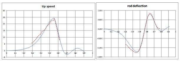
I modeled the Paradigm cast and included the possibility for the caster to ease his grip at the end. Below you can see the comparison between the model and records (dotted lines), for tip speed, rod (perpendicular) deflection, and rotation speed:
The rebound you can see below is the result of the model, not an input. The input stops at t=0.6s. The model uses another spring and a damper at the wrist level; they represent a “mechanically relaxed” grip. The motion induced by the counterflex of the rod is then controlled by the characteristics of the spring and the damper.
The energy and power history are given below. For the time being, the wasted energy (damping forces) is not included in the figures, so this will change once I can incorporate them, mainly after the line is released. Before that time, their contribution is small.
Torque model
One difficulty remains to model the loop formation. I am pretty sure it has a damping effect on the rod, but for the time being, I cannot model that properly. There is a negative torque surge which last 0.01s (I did not illustrate it completely in the graphic). It could be the result of the model used for the “relaxed grip”, since the rebound is influencing that moment of the cast.
I added what could be the information coming from a strain gauge at the hand level. It tells you the loading / unloading / counterflex story of the rod.
The torque (the scale is Nm) becomes negative when decelerating (from 0.45s to 0.6 s), although it is eased by rod unloading in that cast, you can see that there is a good synch between the timing of unloading (from 0.45 s to 0.57 s) and the one of the rotation from the caster, but I can simulate situations where this is no more the case. Then the torque increases to a positive value after loop formation and induces the rebound forward. The “flexible” grip I am using from 0.6 s cushions that rebound. If I add a reel in the system, the overall amplitude of torque increases. The strong vertical changes are due to the modeling of rotation speed, with no smooth change in between the different phase of acceleration and deceleration, up to 0.6s. It is the same for line launch, which is very brutal here (close to 0.56s on the graphic), and is likely one of the causes of the downward surge in torque.
The results are influenced by the timing of the unloading; here we have an example of a rather “easy” deceleration, with a small negative value until the line is released. Does it represent reality? Is it an explanation corresponding to observations that the cast is easy to stop or not? After that, the model will be influenced by the energy used for damping the system, but the counter flex seems correctly modeled (positive torque corresponding to a forward rotation, then negative torque acting against the counterflex to bring it to zero).
This is not the end of the story.
Merlin
Fly rods are like women, they wont´play if they're maltreated.
Charles Ritz, A Flyfisher's Life
Nearly a month without news, but now there are. I studied more carefully the way to calculate the kinetic energy of the rod and I think it is OK now. I updated my model which includes a rebound and what I find is that I get a limited surge in negative torque as the rod counterflexes. By comparison to my last post, the main differences lies at the end of the cast, when the computed torque comes close to the static torque in the rod (the green strain gauge curve), and that makes me feel better.
It seems to match Grunde's observation. I sent the technical material to Grunde and Gordy, now let's see what they think about that.
The fact that the elastic energy eases the deceleration of the rod is still valid, but this is not very large even for heavy loads.
Merlin
Fly rods are like women, they wont´play if they're maltreated.
Charles Ritz, A Flyfisher's Life
Hi guys, a fascinating topic. Could it be that we do both? That the "stopless" cast has no positive stop and that most false casting had a very high positive stop, even pullback? That's certainly how it feels to me when I cast. Of course feeling isn't measuring!
The stopless cast idea came up to my mind since I can simulate casts for which the true stop occurs after the rebound. The rotation speed before the rebound can be positive (stopless), nil (stop) or even slightly negative (pullback). This does not change the line launch speed. It changes the peak (negative) value of the torque surge in the model. That may mean that stopless cast feels better to the angler since the amplitude of the negative torque is less than for a stop and even a pullback.
Some casting analyser records do show similar situations: stopless (small positive rotation speed before the rebound), neat stop (zero speed) or tiny pullback (limited negative rotation speed for a very brief period of time before the rebound). Mathia's cast which we simulate here is nearly "stopless".
The model can be tuned to figure out these different situations, it all depends on the timing when I decide to let the rod drive the cast, no more the caster.
Modeling is not measuring either, that's the difficulty.
Merlin
Fly rods are like women, they wont´play if they're maltreated.
Charles Ritz, A Flyfisher's Life
That the "stopless" cast has no positive stop and that most false casting had a very high positive stop, even pullback?
Paul,
Even the "stopless" cast requires the application of some negative torque to slow down and stop the rod. Otherwise we would just continue to increase the rotation velocity and drive the tip into the ground.
I think the difference in feel comes from the deceleration rate you use to slow down the rotation rate in the two different styles. The amount of additional rod rotation from MAV to RSP1 is much larger in the 170 style versus the additional rotation in a conventional casting style that you get with a positive stop.
The deceleration rate (and stopping time) will be related to the applied torque. As noted earlier:
Noel measured the deceleration rate that Tim Rajeff applied in one of his casts to be -7400 deg/s^2. That means the negative torque Tim applied to stop his rod was about 7400/4000=1.8 times more than the negative torque Mathias used in the Paradigm cast.
I have not seen deceleration values that are applied in a "stopless" cast but I would expect it would be much less than the -3000 to -6000 deg/sec^2 you see in conventional ones. Thus you are applying much less negative torque in the "stopless" style which gives a much different feel to the cast.
Gordy
"Flyfishing: 200 years of tradition unencumbered by progress." Ralph Cutter
The torque from the caster on the rod handle should follow she "strain gauge curve". Force moments from the caster on the rod at the butt will be matched exactly opposite elastic forces (and thus bend) of the rod itself (this is Newtons 3rd law).
Therefore I simply don't believe results like these with abrupt jumps and torque out of phase with the rod bend. (Yes I'm well aware of the fact that Merlin have improved his model, but the results are still not following the bending moment curve of the rod butt).
So I think this one is still valid
grunde wrote:I (like Server Sadik) believe that (at least) the first part of the rapid decceleration is caused by the unloading rod, and not by an active stop by the caster.
Cheers,
Grunde
"Essentially, all models are wrong, but some are useful."
George E. P. Box