For mass tuning, I will wait for Gordys explanation
Vince,
There is only one spring in the form of the SHO that Merlin uses in his model. Consequently there is no mass tuning involved as there would be for the tuned mass damper that has two springs and two separated masses.
The mass of the line will change the loaded frequency of the rod/line system but as shown above it does not impact the damping that is related to the dimensionless material loss coefficient. Phillips noted that for his damping measurements of graphite rods the viscous damping coefficient for graphite rods is around .02 to .03 kg/s. My KK blank had a smaller value of around .01 kg/s, but regardless it has a very small effect in how the rod responds to the forcing input from RSP0 to RSP1.
Gordy
"Flyfishing: 200 years of tradition unencumbered by progress." Ralph Cutter
My apologies for lots of poorly articulated questions. You both have the advantage of a couple of years work and a working model to refer to. In comparison, I am trying to run simaltaneous calculation in my head as I follow your text explanations. The other problem I have is that I cannot visualise the timeline for your cast.
I am not wrapped around the axle on the damping co-efficient, I'm happy to accept whatever figures that you have. I have been interested in zeta because it gives a good indication of dynamic system behaviours.
However, I am puzzled by the damping ratio figures that are coming out. I get critical damping for a value of about 0.1g of mass and I cannot force the system into overdamping.
I have picked off k=0.74, c = 0.025 and am varying the mass from 0.0001 to 0.013.
But I can go outside put a 5wt line on a 2wt rod and it will be overdamped into a noodle. I cannot reconcile the difference between the zeta calculator values of 0 to 1 and a real life overloaded rod, it is counter intuitive.
The mass tuning question was the same issue from another direction. I can take a rod from underlined to overlined and somewhere in between the rod tip force hits a peak and I will achieve the best distance cast.
In post 1, I can see how the input effects the output but not how the value of mass effects the ouput. If Merlins model is not able to do this without modification, it could keep me busy for a while.
I am not wrapped around the axle on the damping co-efficient,
and
However, I am puzzled by the damping ratio figures that are coming out. I get critical damping for a value of about 0.1g of mass and I cannot force the system into overdamping.
Vince,
I think you may be confusing the relative damping ratio (zeta=.025 for a graphite rod and zeta=1 for critical damping) with the exponential damping coefficient that is used to scale the velocity term in the ODE for the SHO. Thus I expect you found the exponential damping term used in the ODE was equal to 1 for a .1g line mass, but that means the loaded frequency also increased significantly to f=1/(2*pi)*sqrt(.74/(.003 +.0001))=2.46 Hz or omega_0=15.45 rad/sec.
Using the damping ratio zeta that comes out of this formulation of the ODE
I get:
since the mo of the rod which equals 3 g will not be changed by the line mass.
That gives a damping coefficient value of
c_exp=2*zeta*w0=2*.025*15.45=.7725 rad/sec.
Did you assume different c , k and mo values to come up with a c_exp factor of 1.0 or does that c_exp term have nothing to do with what your were calculating?
The material damping factor that might impact the spring velocity in the rod from from RSP0 to RSP1 is so small that you could just ignore it, and it would not appreciably affect the predicted line speed. Grunde did not include a damping coefficient in his runs for the Paradigm rod, and yet predicted nearly the same line speed (to within .1m/s) as Merlin had with his zeta=.025 factor. Therefore you might want to quit obsessing about how the damping factor affects Merlin's model. It is a very small effect and as Grunde did, it can safely be ignored in order to get meaningful first order results.
The impact of line mass you and Paul are talking about on after bounce vibrations has to due with reducing the 1/2*mo*v^2 KE in the rod that drives the counterflex magnitude. More line mass will decrease the loaded frequency of the rod/line SHO which will reduce the spring velocity as the rod goes from MRF to RSP1. As noted earlier that spring velocity will not be affected a great deal by the relative damping factor and/or the damping coefficient.
A lower frequency will reduce the velocity of the moving mass (especially at the tip) in the rod. Lower velocity will produce considerably less KE in the moving mass of the rod since the KE will vary as the square of the velocity. Less KE at RSP1 means there will be less counterflex and thus less after bounce vibrations. To first order it is that simple.
Relaxing the grip at the right time will also affect the damping factor used to get an approximate exponential damping coefficient used in the model from RSP1 to MCF, but that factor is still less than the critical factor factor of 1. I think Merlin said he uses a zeta factor of .6 in that time range along with the much higher natural frequency of the rod (f=2.5 Hz) to come close to the observed counter flex deflection in the Paradigm cast.
I can see how the input effects the output but not how the value of mass effects the output. If Merlin's model is not able to do this without modification, it could keep me busy for a while.
Time to open another bottle of wine. Merlin's model is all about how we change the input forcing function to match up with the loaded frequency that results from different line masses and rods with different spring constants and effective masses.
Thus thinking Merlin's model does not take into account the effect of different line masses indicates to me that you do not understand how it works. For technical details I would refer you again to this thread that discusses the ODE used in this simple (or not so simple) 1-D model of casting. There should be enough meat in that topic to go with a bottle of wine for you.
Gordy
"Flyfishing: 200 years of tradition unencumbered by progress." Ralph Cutter
Your opening statement is the one that is causing the confusion
I think you may be confusing the dimensionless damping factor (c=.025 for rod and c=1 for critical damping) with the damping coefficient that is used to scale the velocity term in the ODE for the SHO.
The constant of proportionality used in the SHO and its associated calculations is C and is measured in N s/m, it is not dimensionless.
The other term is the critical damping co-effieicnt which is ofter termed Cc is the term sq rt 4 m.k and is also measured in N s/m.
The dimensionless damping ratio or zeta or the damping rarto is c/Cc or c/2 sqrt m.k
This is a copy of a module I did about 25 years ago and covers the subject well:
When you say c=1 for critical damping, what you are doing is stopping your damping module damping. In a dashpot you have closed off the hole. It is not the dimensionless damping ratio.
Using a 31g mass you have a zeta of 0.261 so it is very underdamped. Your 31g (478 grains) line equates to a line weight of somewhere between 13 and 14, what rating is your rod for it to be so underdamped? This is what I am finding odd.
I think if you re-read the posts, I pointed out to Merlin the change in zeta as a result of mass change. Both Merlin and yourself are confusing the terminology and seem to have the same idea that mass does not change zeta. Please read posts 142 and 144.
Lower frequency will reduce the velocity of the moving mass (especially at the tip) in the rod. Lower velocity will produce considerably less KE in the moving mass of the rod since the KE will vary as the square of the velocity.
Prior to the cast, I agree that a higher mass resultis in a lower frequency but the amplitude of your oscullation is also increased. That is why I talk about tip force and not tip frequency.
If force = ma , we have inceased m because of the line weight and we have also maintained or increased a because the tip has further to travel.
When you have cast the line, the frequency will return to the natural or unloaded frequency. The distance of the cast does not only depend on frequency but also mass of the line and the amplitude of the deflections. If line speed was only dependant on frequency then a heavier line mass would always result in a shorter cast.
I will look at casting input after we round off this discussion because it is relevant. As ever, I am not here to throw rocks. My last job in the RAF was flight trials and it involved validating models by testing. That is all I have done with the discussions on damping and line speed.
Confusion in notations is still there (but not in my model).
I think if you re-read the posts, I pointed out to Merlin the change in zeta as a result of mass change. Both Merlin and yourself are confusing the terminology and seem to have the same idea that mass does not change zeta. Please read posts 142 and 144.
Post 144 I explained to you that this could be an option if you try to mimic air drag. Internal material dampening is small, if not negligible as mentioned by Gordy. The problem is that you mention zeta to be influenced by m. You used Paul’s example to reinforce the perception you have that damping increases with m. OK, let’s take this as a better approach of reality for modeling drag forces, now as we increase m, the damping ratio is vanishing in the basic equation: c remains the same but zeta goes down because m is increasing: how can you increase it while increasing m? This contradiction, although raised in post 144 did not draw your attention.
When you have cast the line, the frequency will return to the natural or unloaded frequency. The distance of the cast does not only depend on frequency but also mass of the line and the amplitude of the deflections.
This is not the result of solving the equation, so please detail your argument quantitatively rather than qualitatively.
If line speed was only dependant on frequency then a heavier line mass would always result in a shorter cast.
Why? It seems you have entered the issue of the fly line flight here, and I do not think that is matching reality: if I cast a #8 and a #5 with the same launching speed and loop size, the #8 will go further. The solution of the SHO is only depending on the frequency, just because of the final equation in post 153.
You are telling us that zeta is depending on the mass of line and that disturbs the frequency fit (in the above equation, if zeta is a constant then the solution only depends on the frequency represented by omega0), but for the time being, you are telling that zeta diminishes with m, so how could that increase the damping of the system? See the contradiction? We can take a better estimate of zeta on board, but which one? For the modeling, it has to be a best guess remaining constant all along state 1 of the cast. You can have a set of different values of zeta with different values of m, this is not a problem, but try to give us your best guess in that field. The estimate zeta = c (constant for the damper) / 2 sqrt (mk) does not work at all for the time being. It just says that the damping action is diminishing as the mass increases.
Merlin
Fly rods are like women, they wont´play if they're maltreated.
Charles Ritz, A Flyfisher's Life
Both Merlin and yourself are confusing the terminology and seem to have the same idea that mass does not change zeta.
Vince,
Thank you for the correction as I had it all wrong.
I was confused about terminology (Merlin was not) but I think Merlin has straightened me out on the fact that the material damping factor that Phillips uses in his book is related to the relative damping ratio zeta not the viscous damping coefficient c.
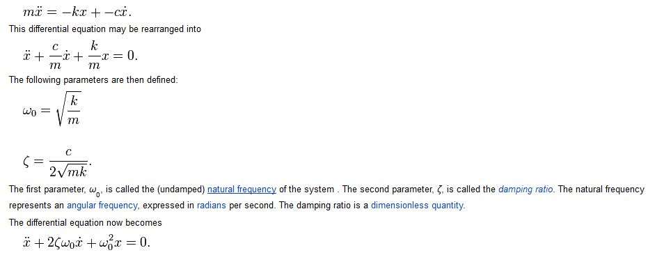
I agree that I was confused about terminology, so let's agree on a common set of definitions and use the same set of relationships that are given in Wikipedia for this form of the ODE.
The viscous damping coefficient , c, is used to compute the damping force that varies with the velocity term in the SHO model.
Fd=-c*v or Fd=-c*dx/dt
It has a dimension of Newton-seconds per meter or kilograms per second.
c is related to the dimensionless relative damping ratio of .025 for graphite rods and will vary with the square root of the effective mass and k of the rod such that:
c=zeta*2*sqrt(k*m)=zeta*2*sqrt(k/m)*m or c=2.*zeta*w0*m.
When the rod is oscillating at its natural frequency of 2.5 Hz k would be .74 N/m and m would be the effective mass of the rod which was .003 kg for the Paradigm rod.
As a check those k and mo values give a natural frequency of f_n=1/(2.*pi)*sqrt(.74/.003)=2.5 Hz or an w0=15.7 rad/sec. Thus when the rod is hard clamped the viscous damping coefficient would be c=.025*2.*sqrt(.74/.003)*.003=2*zeta*15.7*.003=.002355kg/s.
The damping ratio (zeta) depends on c, k, and mo and for the Paradigm rod was computed to be:
zeta=c/(2*sqrt(k*m))=.002355/(2*sqrt(.74*.003)) = .025 (dimensionless)
The exponential damping coefficient for the time domain exponential weighting term in the solution of the ODE is equal to
c_exp=c/2=zeta*w0 =.025*15.7=.3925 rad/sec.
Simplifying terms c_exp is also equal to c/m/2 or .002356/.003/2=.3925 rad/sec.
In the under damped case the exponential damping coefficient on the velocity term will give an exponential roll off in the amplitude of the frequency oscillations with time that is equal to exp(-t*c_exp) or exp^(-t*zeta*wo)=exp(-.3925*t).
Does that set of definitions and values fit with your understanding of the parameters used to model the SHO properties of a rod?
Gordy.
"Flyfishing: 200 years of tradition unencumbered by progress." Ralph Cutter
Thank you for your repsonse. The 31g was misread back on to the board by me. At a total of 3.1 and 13g, I get the same zeta as you both undersamped. At 31g, damping is near non-existent at 0.08.
In terms of definitions, this still troubles me:
The viscous damping coefficient ( assumed to be c=.025 kg/s for the Paradigm rod) is the factor that is independent of the mass.
If you check this reference, c is not independant of mass:
When a damped oscillator is subject to a damping force which is linearly dependent upon the velocity, such as viscous damping, the oscillation will have exponential decay terms which depend upon a damping coefficient. If the damping force is of the form:
F(damping) = -CV
This link provides another form and pitches the maths to your level:
Where alpha is the constant for mass proportional damping
and bravo the constant for stiffness proportional damping
and Page 4:
For each natural frequency of the system, wa, the effective damping ratio is (see slide for formula):
– Thus, mass proportional damping dominates when the frequency is low,
and stiffness proportional damping dominates when the frequency is high.
– Recall that increasing damping reduces the stable time increment.
Merlin, you are both throwing a lot at me here but I will try to keep my response clear.
At the moment, zeta is decreasing with mass. That does not fit the real world. Putting 31g on a rod tip will kill any oscillation very quickly. The reason that zeta does not fit the real world is because in the zeta calculation c is a fixed value of 0.025.
As I have shown in the links above c is not a constant, it varies with either velocity or mass depending on which form of the equation you want to use.
The question is what conditions was the value of 0.025 calculated for. I suspect it is 1g acceleration.
Why? It seems you have entered the issue of the fly line flight here, and I do not think that is matching reality: if I cast a #8 and a #5 with the same launching speed and loop size, the #8 will go further.
I have stayed well away from aerodynamics and loops, except to say it would take a complex solution such as finite element analysis to tackle it. I have only ever meant to refer to tip forces. I mentioned line weight to try and put the context in the real world.
The reason that I re-visited it is because I disagreed with Gordys statement
Lower frequency will reduce the velocity of the moving mass (especially at the tip) in the rod.
Lower frequency will reduce the acceleration but the wider arc because of the additional mass will increase the time and distance that the tip travels so the maximum velocity at the tip may be higher that the unloaded case.
Here is a question that I will put to you both:
If you change the mass on a rod, it changes the frequency. State 1 loaded and 2 unloaded is an example.
Your opening statement is the one that is causing the confusion
Vince,
Thank you for pointing out I was very confused in that post. Merlin let me know that the material loss factor given in Perkins book was related to the relative damping factor zeta, not the viscous damping coefficient as I had thought. The real viscous damping coefficient is about an order of magnitude smaller than the relative damping factor so it was a big error.
I hope the terms in that post (#153) have been corrected using the nomenclature in the above post.
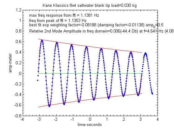
Thanks again. I now know I was getting the zeta damping ratio in the calculation I make from the best exponential fit that I make to the oscillations observed in a clamped rod as shown below:
In that form of the ODE zeta=exponential wt factor/w0.
Gordy
"Flyfishing: 200 years of tradition unencumbered by progress." Ralph Cutter
No problem. The complexity of the problem and the forum environment is tailor made for misunderstandings. It is very easy to get a bit heated and I know I try to keep language simple to avoid errors but it does read as though I am banging the desk.
One of the reasons I like to see the damping ration zeta is because it draws c,m & k together and by extension f. If all is not well with zeta fitting simple real world expamples then I consider that I need to look at something.
Hopefully, you have seen my missive on c being a variable.
regards
Vince
I just looked up a Kane Klassics and it's not graphite
Lower frequency will reduce the acceleration but the wider arc because of the additional mass will increase the time and distance that the tip travels so the maximum velocity at the tip may be higher that the unloaded case.
Vince,
I think that I have been careful to note that the velocity involved in the 1/2*mo*v^2 calculation for the KE of the moving mass in the rod is related to the spring velocity of the rod.
The spring velocity at RSP1 depends primarily on the maximum tip deflection and loaded frequency of the rod/line system and secondarily on the deceleration rate applied to stop the rotation of the rod.
Thus it not the same as the line velocity that does depend on the arc and the deflection force from the rod.
Why does the frequency change?
I take it that is a rhetorical question, since you already know the answer, but it has to do with the conservation of the PE and KE energies in an SHO with no forcing inputs.
A better question is why does it vary as sqrt(k/(mo+m_line)) rather than sqrt(k/m_line) as you might expect based on the equation given for the SHO in Wikipedia?
Dr. Lewin explains why the mo of the rod must be included in the loaded frequency calculation 27 minutes into this MIT lecture.
Gordy
"Flyfishing: 200 years of tradition unencumbered by progress." Ralph Cutter
Rayleigh coefficient is a very interesting stuff. I took some time to investigate that and here are the findings. First, this is related to internal damping, and the damping ratio can be written as
Damping ratio = alpha /omega /2 + beta*omega /2
While the damping coefficient is = alpha * mass + beta * stiffness.
OK, so I played around with actual values, like for example what we get from the vibration damping of the first mode to try finding out alpha and beta values. The fact is that it is not straightforward and in practice this needs quite complex calculation for structures when you know their harmonics. You have got to use a number of harmonics to get a stable and unique solution for alpha and beta. Here is an illustration extracted from a publication, the “frequency” is in rad/sec, and the range corresponding to fishing rods is between 7 rad/s and 16 rad/s approximately.
Nevertheless we can have a look at the possible ranges for alpha and beta. Let’s look at what I got for a typical 9 feet rod designed for a number 5 line:
If alpha = 0, beta = 0.0032
If alpha = 0.39, beta = 0.0016
If alpha = 0.78, beta =0
We may have rods sensitive to mass damping, others to stiffness damping, I cannot tell today but this opens a new area for investigation. Using the three first harmonics of a typical rod I can say the following:
In the first case, where stiffness damping is dominant, the damping of the third NF can be significant (damping ratio above 0.15), especially when the rod is not loaded (state 2). That makes me think about very fast rods when you just kick them a little bit in the shop they dampen quickly.
When mass damping prevails, this is just the opposite, higher NFs have less damping, very small indeed (0.004). Is this a source for wobbling?
In the intermediate situation, the stiffness character is dominating. So the question is: where are our rods?
If we look at the first harmonic, the values can range from 0.01 to 0.03 for the damping ratio without load. Still small, and when we take mass on board, let’s say 60 feet of line for some 20 grams, the maximum value is 0.78 *0.023 (mo is included) = 0.018 for the damping coefficient, which corresponds to something like 0.07 for the damping ratio: far from being critical (1).
The conclusion for me is that this approach is interesting for state 2 vibrations problems. Thanks a lot for bringing that on the table. For state 1, the drag effect is dominant, as we can see below.
I estimated the effect of air drag on the rod close to RSP, when tip speed is maximum. That can give a damping coefficient about 0.065 for a maximum tip speed of 25 m/s. Now if I imagine the mass being 13 grams and the stiffness 0.74 N/m, that would correspond to about 0.33 for the damping ratio at RSP. Pretty high. At the beginning of the cast the damping effect is nil (no speed), so it is not easy to define what could be an “average” damping ratio for a cast, since the SHO model needs one single value.
The conclusion of this is that when you witness a more pronounced damping effect as you cast a heavier line, it could well come from air drag since you use to cast such line at higher speed. At the very beginning of state 2, we have the same influence of air drag, and it disappears at MCF. After that we enter the material damping effect area again.
Merlin
Fly rods are like women, they wont´play if they're maltreated.
Charles Ritz, A Flyfisher's Life
I did not mean to be facetious but I read the remark in isolation and only recalled the discussion being on frequency and not amplitude. I am guessing it is a historical thing for you and Merlin and is long laid to rest.
I take it that is a rhetorical question, since you already know the answer, but it has to do with the conservation of the PE and KE energies in an SHO with no forcing inputs.
A better question is why does it vary as sqrt(k/(mo+m_line)) rather than sqrt(k/m_line) as you might expect based on the equation given for the SHO in Wikipedia?
The mo + mline made sense to me as soon I saw you using it. It might sound odd but if there was no mo, the tip would not oscillate without a line.
The question was slightly rhetorical but a bit more basic than you think. The PE and KE conservation of energy is the key but the mechanism is managed between the spring and the mass (this is how I rationalised the mass as an inductor). The damper regulates the rate of exchange of PE and KE between the mass and the spring. This is why I looked critically at the value of c.
Merlin
That is excellent work in such a short time and I think that the non-linearity is very interesting because it is where we are operating.
We may have rods sensitive to mass damping, others to stiffness damping, I cannot tell today but this opens a new area for investigation.
It should be achievable to reduce the number of possibilties. If you look at the reference in my last post:
– Thus, mass proportional damping dominates when the frequency is low,
and stiffness proportional damping dominates when the frequency is high.
This is where I have to dress myself in sackcloth and ashes because I have made a monumental cock-up in my analysis of the problem. I have limited the scope of my analysis because when I broached the subject of control engineering, I thought I may get a damn good ignoring if I pursued it directly. I have been doing it through the back door by discussing zeta but only considering 2 of the 3 elements in the system, the rod and line, not the shaved monkey that waves the rod.
The other element of zeta that I dumped in this process was stability, it is more important than damping and was why I came to this thread. The penny dropped last night. The rod and mo are underdamped and barely stable. As you add mline, zeta drives more towards zero it becomes more unstable. It's instabiltiy that is the issue with overlining not overdamping. So a rod and line alone is an underdamped, marginally stable, low frequency low energy system. You can drive a system into instability by positive feedback, such as an amplifier and microphone, and zeta would go to a negative value. I think if we do that the rod breaks.
In control engineering and flight test terms, low frequency, low energy, marginal stability is a region to avoid. If it interests you look up phugoid and dutch roll or watch this video about the 16 second mark (note the frequency):
When we pick up a rod and line we are doing several things all aimed making the sysem more stable. We increase the system energy and rod velocity using positive feedback (through hand and eye). To prevent system runaway, we back off the stabiltiy using the damping of the caster and the rod combined to stabilise the system. This is how we achieve critical damping.
Now we should also consider the following expression
zeta = c(caster) + c(rod)/ 2sqrt(mk)
c(caster) could be interesting as it would likely work much like c(rod) just on a larger scale.
It should work for both states, we just need a combined c that makes zeta = 1 for both states. The proprotion would change between caster and rod for each state.
If you can swallow the zeta and stability explanation, I could start to open up stability margins.
It might sound odd but if there was no mo, the tip would not oscillate without a line.
Vince,
Does that imply the K would have to be infinite? I realize that dividing by zero mass would have an undefined result in the frequency equation, but I think your interpretation of that "unknown" situation is rather odd.
The damper regulates the rate of exchange of PE and KE between the mass and the spring.
That becomes a factor when the damper has a reasonably high value, but is not the case for a fly rod since its zeta is so small.
I think you know the rod is not acting as a big spring in casting. The caster is applying an external force to the rod/line system. Therefore there is no conservation of energy going on between the PE in the rod and the KE of the line, as there is with a stand alone SHO that has no external forces.
Gordy
"Flyfishing: 200 years of tradition unencumbered by progress." Ralph Cutter
Does that imply the K would have to be infinite? I realize that dividing by zero mass would have an undefined result in the frequency equation, but I think your interpretation of that "unknown" situation is rather odd.
All I did was a 1st approximation - "there must be a rod mass to be considered or the equation would not work". However, I am not sure that I would have come up with a way to measure it as you did.
That becomes a factor when the damper has a reasonably high value, but is not the case for a fly rod since its zeta is so small.
It all depends on what you want to use your tool for. If it is for general trends, I absolutely agree with you. You could also use 3g as Mo for all rods that you analyse because for trends the actual value is not critical. But as Merlin pointed out with Pauls tip bounce discussion, when the casing stroke ends in a hard stop or even insufficient caster damping then the value of c(rod) becomes more important. Your model matching has been conducted against very technically competent casters, not against stick waggling dumplings like me.
For me the SHO is only of interest for building a mental model that I can carry in my head and I am near to the point now where I will not participate in the thread because I have a sufficient understanding for me to go fishing with. If you want to use the tool for analysis then I suggest that you would want to maximise fidelity.
A good illustration is Lasse video with the 2 rods strapped together. It's worth a look with fresh eyes based on the last zeta equation I put up.
The input, tip velocity, caster damping and mline are all the same. The variables are m0 and c rod. At first, I thought that k was different for the top of one of the rod sections but watch the action angle as he picks the rod up at the beginning of the cast. It is worth looking at the tip bounce and what is happening on the line.