
Bernd,
You can't "feel" acceleration because the body does not have a "feel acceleration" sense. The closest that it posseses is the inner ear which can sense "change in acceleration" in the cerebral cavity. You are being accelerated all the time and you can't sense it. Gravity, centrifugal force from the earth rotation and from the acceleration of the earth around the sun and from the sun in the galaxy and the galaxy in the universe. You can feel the force of the ground on your feet but you cannot feel the acceleration. So to "strive for constant acceleration" would be impossible. You could, however, strive for constant force (or constant forces that produce constant torque) and achieve constant acceleration.
We have struggled on this board for a long time in this matter. I know Gordy doesn't like discussions regarding "feel" because it cannot be quantified and boxed in neat equations. You can only measure or try to calculate derived elements of motion and speculate on what the caster was "feeling" or trying to do. But at the end of the day, "feeling" is all that reallly counts and all the equations on earth can never "feel" anything no matter how precise or repeatable or accurate they are.
I tried to get to handle force in my models thinking that if I could look at those forces in a cast I could determine what the caster would be feeling and thus determine his intent. Even with that data, I couldn't make the jump from those forces to the casters brain so I gave up trying.
I think the only way that you might be able to do that is to instrument a rod handle and communicate the measured data to a heads up display so a caster could watch real time what was happening to whatever derived quantity he desired to study and compare it to what he was trying to feel. That is way beyond me but I'll bet the expertise exists on this board to try to get there.
Bob
PLEASE NOTE: This is the Archived Sexyloops Board from years 2004-2013.
Our active community is here: https://www.sexyloops.co.uk/theboard/
Our active community is here: https://www.sexyloops.co.uk/theboard/
Smoothness - and the use of the CA
-
Bobinmich
- IB3 Member Level 1
- Posts: 606
- Joined: Fri Sep 14, 2007 4:09 pm
- Location: Rochester, MI
- Contact:
Bob Bolton
www.HATofMichigan.org
www.HATofMichigan.org
-
gordonjudd
- IB3 Member Level 1
- Posts: 2214
- Joined: Mon Jul 10, 2006 12:14 am
- Location: California
- Contact:
Again Bruce and Noel ask all these casters to show their best loops. He did not ask for smoothness or everything like that.
Bernd,
This may be a case of "dueling" data, but I have have not seen data that backs up some of these "expert" claims.
Bruce's sampling of casters is much broader than mine, but if exceptions can break the rule, then what I have measured in Chris Korich's cast would say an expert caster does not necessarily have to use a linear velocity profile in their accuracy casting.
I don't know if Bruce considers this example of a using a linear velocity profile to produce what he considers to be an expert loop, but anytime the fly gets below the rod leg is asking for trouble in windy conditions.
I have watched Chris cast many times, and I have never seen him produce a tailing loop even though his smoothness ratio may be higher that the 8 value Bruce considers to be an upper limit. You can bet that his fly leg is always above his rod leg as well. I used to get dumps with the leader not straightening out completely, but I have never seen it happen with him or Steve.
In tournament games I mostly saw very good casters striving for total high line speed (in order to match windy situations as well).
I think that is true, and yet in the dry fly game these guys can hang a fly over the target while they are adjusting for distance on a target, so they are definitely in the "Cinderella" range (not too little or to much line speed) in order to do achieve it.
The Golden Gate casters have very windy casting conditions at their pond, and thus may use more line speed than others to deal with the wind. That may be part of the reason they do not use constant acceleration, but their style is certainly productive, as they tend to dominate the tournament casting rankings in the US, wind or no wind.
Gordy
"Flyfishing: 200 years of tradition unencumbered by progress." Ralph Cutter
-
gordonjudd
- IB3 Member Level 1
- Posts: 2214
- Joined: Mon Jul 10, 2006 12:14 am
- Location: California
- Contact:
If we would call linear acceleration to be an ideal instead of constant acceleration as just one form of linear acceleration, I'd totally be fine with that.
Way more specified than just "smooth".
Would that make more sense?
Bernd,
I would not just limit it to being linear, as you can see Chris had a quadratic variation in his acceleration curve. As I remember Paul's acceleration function in one of his distance casts had a t^3.3 exponential change with time.
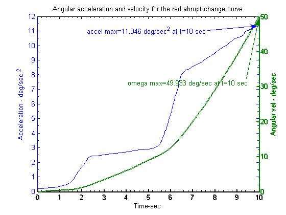
The important factor in terms of "shocking" the rod and creating tailing loops are sudden changes in the applied acceleration. A good example of such a "shock" is the red abrupt change curve you posted above.
I suspect that was an hand drawing curve rather than a measured one, but you can see there is sizeable change in the acceleration in that curve at around t=3 in that curve.
I modified the scale on that curve to get more representative values (I don't think any forward cast would take 10 seconds to perform) to show more representative values as shown below.
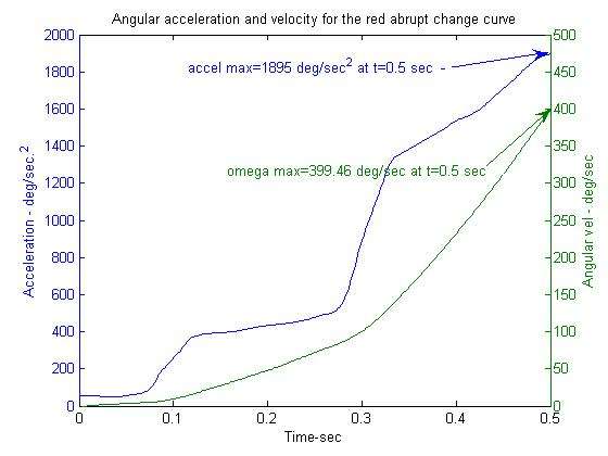
You can see there is big change in the slope of that curve at around t=.3 seconds where the acceleration changes from around 500 deg/sec^2 to 1400 deg/sec^2.
Engineers call the change in acceleration vs time "jerk." Here is the jerk that corresponds to that abrupt change curve.
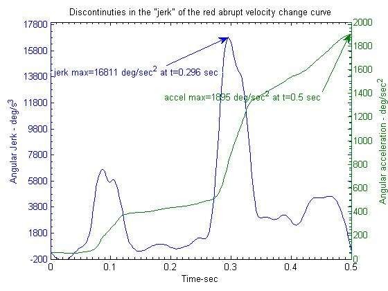
If you were to compute the jerk in Chris' cast you would find it had a nominal linear slope, but it would not have the big humps that are shown in this plot. Thus applying smoothly varying acceleration that is devoid of big humps in the resulting jerk is a reasonable concept to me.
As Chris demonstrates you can have large changes in the applied acceleration and not produce tailing loops as long as those changes are devoid of big jerk changes. However shocking the rod with abrupt changes that produce big jerk humps will cause the tip to dip suddenly and produce troublesome transverse waves in the line.
Gordy
"Flyfishing: 200 years of tradition unencumbered by progress." Ralph Cutter
-
Bernd

- IB3 Member Level 1
- Posts: 2204
- Joined: Sat Mar 11, 2006 10:55 pm
- Location: Hamburg, Germany
- Contact:
Hi Gordy,
to me this looks like Chris was using a relatively compact arc and using a pretty strong rate of acceleration to reach max velocity. Typical for accuracy (tournament) casting I think.
Am not sure but the smoothness ratio doesn't seem to be very high to me?
Greets
Bernd
Bernd Ziesche
www.first-cast.de
www.first-cast.de
-
gordonjudd
- IB3 Member Level 1
- Posts: 2214
- Joined: Mon Jul 10, 2006 12:14 am
- Location: California
- Contact:
Am not sure but the smoothness ratio doesn't seem to be very high to me?
Bernd,
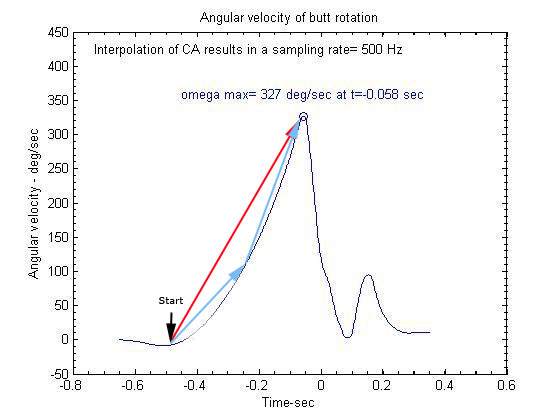
We will have to wait until Bob can get the actual limits they use for their linear fits to compute the slope, but let's assume it is the ratio of angular acceleration calculated at the 10% and 90% points in the cast. If you assume the cast started at t=-.5 s and MAV was at -.058 s, then the 10% point would be at t=--.45 sec and the 90% point would be at -.1 sec.
Here is the computed slope of that velocity curve which gives the acceleration vs. time curve needed to calculate the smoothness ratio for that cast of Bruce's (not Chris Korich's) expert 50 file. I don't know what the lines you have drawn represent, but they do not give the intantaneous slope at the desired -.45 and -.1 seconds time points.
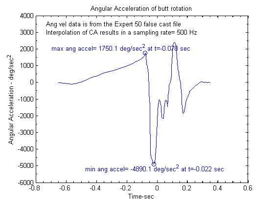
Just eyeballing the acceleration values at t=-.45 s (250 deg/sec.^2) and t=-.1 (1400 deg/s^2) that would give a smoothness ratio of 1400/250=5.6.
Doing the same thing for Chris's acceleration curve I get a value of around 15.
Gordy
"Flyfishing: 200 years of tradition unencumbered by progress." Ralph Cutter
-
Bernd
- IB3 Member Level 1
- Posts: 2204
- Joined: Sat Mar 11, 2006 10:55 pm
- Location: Hamburg, Germany
- Contact:
Hi Gordy,
ok that makes sense if the points are at 10 & 90%. (I just took it somewhere )
)
I don't know how the starting position is taken by the CA.
I just took the point at which rotation starts...
Not sure if that is a good idea since the main rotation may not have started but some slight unintentional rotation in the beginning of the stroke...
Now I understand how the jerking works. Was confusing til I made this excel calculation on my own. (Yes I just put in some numbers free of serious unit):
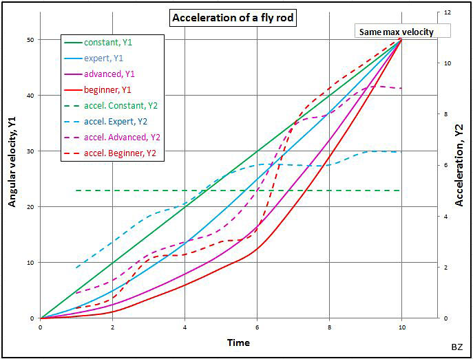
Now which are SMOOTH here? :p
:p
Greets
Bernd
ok that makes sense if the points are at 10 & 90%. (I just took it somewhere
 )
)I don't know how the starting position is taken by the CA.
I just took the point at which rotation starts...
Not sure if that is a good idea since the main rotation may not have started but some slight unintentional rotation in the beginning of the stroke...
Now I understand how the jerking works. Was confusing til I made this excel calculation on my own. (Yes I just put in some numbers free of serious unit):
Now which are SMOOTH here?
Greets
Bernd
Bernd Ziesche
www.first-cast.de
www.first-cast.de
-
Bernd
- IB3 Member Level 1
- Posts: 2204
- Joined: Sat Mar 11, 2006 10:55 pm
- Location: Hamburg, Germany
- Contact:
Watching the the graph showing Chris's acceleration in Post nr. 10 here made me think about using the term smooth for such "jerking" graph.
Why do we strive for an ideal in the art of accelerating a fly rod?
I think because a lot of fly casters are producing tailing issues (too significant waves in the fly-leg) and therefore loosing efficiency in their casting.
The key to tailing issues is the dip (down & up both included) in tip path.
So I think the art in proper acceleration is in achieving
a smooth increase in rod bend to an abrupt stop in order to avoid the tip dipping while having a smooth (and easy) rod hand path, too.
How about:
"Proper acceleration (smooth increase in rod bend) to an abrupt stop."
That way translation and rotation would be included as I understand it. It also should fit with and without hauling.
Greets
Bernd
Bernd Ziesche
www.first-cast.de
www.first-cast.de
-
Bobinmich
- IB3 Member Level 1
- Posts: 606
- Joined: Fri Sep 14, 2007 4:09 pm
- Location: Rochester, MI
- Contact:
I have found that looking at graphs in displacement terms does more to my understanding than does using time. Although the beginning of a cast is very important, more energy is transferred towards the end. That part of the plot becomes needlessly compressed when looking at time as the ordinate rather than displacement (distance or angle, etc.).
This may be just me helping my meager understanding abilities though.
Bob
This may be just me helping my meager understanding abilities though.
Bob
Bob Bolton
www.HATofMichigan.org
www.HATofMichigan.org
-
gordonjudd
- IB3 Member Level 1
- Posts: 2214
- Joined: Mon Jul 10, 2006 12:14 am
- Location: California
- Contact:
Now which are SMOOTH here?
Bernd,
You need to check the way you are taking the derivative of the velocity curves to come up with your dashed acceleration curves. the original dashed lines do not look like the derivative of the solid velocity curves to me. Glad to see that your new corrected curves match up with mine.
Here is what I get for your red beginner y1 curve using your scales.
Any curve that does not have an abrupt change in the slope of the angular velocity curve will be devoid of jerk humps, and thus would have a smoothly varying acceleration curve.
You could take two derivatives of your velocity curves to see what the jerk would be, but your purple advanced y1 curve appears to have a smooth quadratic angular velocity variation to me. The first derivative of a quadratic function would give a linear variation for the acceleration. The derivative of the acceleration would have a constant value with no jerk humps.
"Proper acceleration (smooth increase in rod bend) to an abrupt stop."
Some will argue about the stop needing to be abrupt, but I like the focus on the smooth increase in the rod bend.
Gordy
"Flyfishing: 200 years of tradition unencumbered by progress." Ralph Cutter
-
gordonjudd
- IB3 Member Level 1
- Posts: 2214
- Joined: Mon Jul 10, 2006 12:14 am
- Location: California
- Contact:
I have found that looking at graphs in displacement terms does more to my understanding than does using time.
and
Although the beginning of a cast is very important, more energy is transferred towards the end.
Bob,
What do you mean by a transfer of energy? I do not see where there is any energy transfer going on, rather there is work energy being applied to the line.
In terms of the force over distance curve you can see the work energy applied to the line is a maximum in the region of the cast where the deflection of the rod is around MRF. That point was about 120 ms before RSP1 for the Paradigm cast.
As Grunde showed in his calculations for that cast the maximum power (energy per unit time or force times velocity) was applied at MRF as shown below.
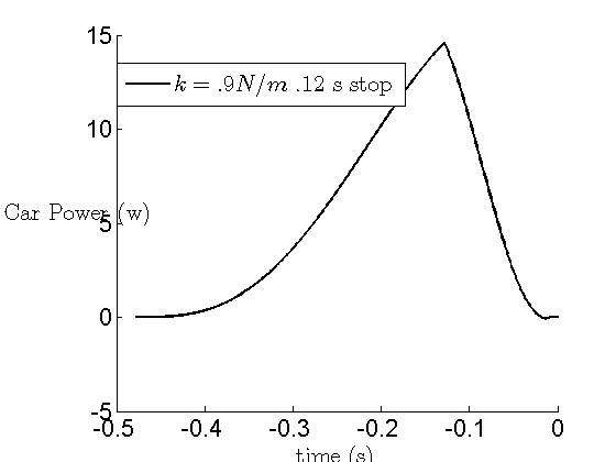
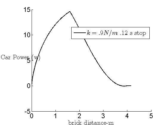
The work energy applied to the line will be equal to the area under the power curve. Just eyeballing that area relationship you can see most of the energy is applied from RSP0 to MRF not from MRF to RSP1.
I would agree that looking at displacement functions can give a better idea of what his going on from a work energy standpoint. Here is the power vs displacement curve for the Paradigm cast. It has a much different look than the same power vs time curve.
Gordy
"Flyfishing: 200 years of tradition unencumbered by progress." Ralph Cutter
-
Bobinmich
- IB3 Member Level 1
- Posts: 606
- Joined: Fri Sep 14, 2007 4:09 pm
- Location: Rochester, MI
- Contact:
Gordy,
I think you understood what I was saying even if you didn't agree with the terms. BTW, I know what kinetic energy is, I know what potential energy is, I know what mechanical energy is, and a bunch more. But my physics instructor never filled me in on "work energy." He only explained work and energy and that work equals energy. Guess he didn't go far enough.
When you look at the elements of motion vs distance for a real cast, it shows a much different picture. If you were to try to define a "constant acceleration" cast and compare it to a "smoothly increasing acceleration" cast, you would look at the derived quantities in that part of the cast after the rod was loaded and all that slack was gone out of the system. Kinda like what you would look at after a switch engine gets all the cars running in the right direction after he backs up and gives everything a big jerk. When I am casting in the dark, I increase the rod velocity until I feel the rod start to load and then I concentrate on how I apply the load from there on to the stop. This is way different than a distance caster applying power as fast as he can without breaking the rod. A distance caster would probably want to apply the maximum force he could for as long as he could to do the most work as he could on the system. If the limiting force he can apply is limited by the rod, he would want to apply that force constantly throughout the cast. BTW this might approach something like constant acceleration. If the rod got stronger through the cast he might increase this force through the cast ending up in something increasing acceleration. If the rod has nothing to do with it, his physical strength might govern how that is applied. But all of this is beyond me and it is much different than what I am striving for in a night cast.
In a night cast I am trying to keep the force I put on the rod handle smooth and constant or maybe a little increasing. But never decreasing. I also try to limit that force to give myself as long a stroke as I can and still get the job done. Lighter loads over longer distances are easier to control and "feel." There's that word again.
Thats why I modified all my models to look at distance rather than time.
Bob
Bob Bolton
www.HATofMichigan.org
www.HATofMichigan.org
-
gordonjudd
- IB3 Member Level 1
- Posts: 2214
- Joined: Mon Jul 10, 2006 12:14 am
- Location: California
- Contact:
I think you understood what I was saying
Bob,
Actually I did not understand what you were saying.
Your use of energy transfer at the end of the cast gave me the impression that you were looking at the physics of casting in terms of the big spring theory.
Guess he didn't go far enough.
The force applied over distance work energy principle has been around for 200 years so I am sure it was covered in your dynamics class. If you are like me it just took a Physicist (Grunde) to remind me of how important that principle is in terms of how line speed is developed in casting.
If the limiting force he can apply is limited by the rod, he would want to apply that force constantly throughout the cast. BTW this might approach something like constant acceleration.
Take a look at this to see how Paul develops line speed (maximum torque applied over a maximum angle) in his distance casting.
It is a far cry from using constant acceleration. From your comments, I don't think your intuition fits with the results that can be derived from Merlin and Grunde's SHO model of casting.
Gordy
"Flyfishing: 200 years of tradition unencumbered by progress." Ralph Cutter
-
Bernd
- IB3 Member Level 1
- Posts: 2204
- Joined: Sat Mar 11, 2006 10:55 pm
- Location: Hamburg, Germany
- Contact:
Hi Gordy,gordonjudd wrote:You need to check the way you are taking the derivative of the velocity curves to come up with your dashed acceleration curves.Some will argue about the stop needing to be abrupt, but I like the focus on the smooth increase in the rod bend."Proper acceleration (smooth increase in rod bend) to an abrupt stop."
thanks for your help.
I calculated the acceleration not only for each unit time but for the whole time til each point on the x-ais.
Have corrected it now.
Since I did not use any function to calculate the numbers instead of "taking them by hand" there is no smooth acceleration curve at all besides the one of the constant acceleration.
The more I think about it, the more I start to like the smooth increase in rod bend idea!
It seems to cover a lot more.
I understand the abrupt stop like this:
casting stroke = rotation + translation in order to form a loop = 100% distance
The smaller the percentage of the distance used to decelerate is, the more abrupt the stop will is.
I see casts in low overall force application but they mostly still have abrupt stops.
I think to use a high percentage of the distance to decelerate easily may result in a collapsing cast.
At least as long as the size of arc matches the length of line. Of course we could use a very short line and a wide arc in order to accelerate the rod and then use a high distance to decelerate the rod and still hit the neccesary max tip speed. However I don't think this would look too good.
Makes sense?
Greets
Bernd
Bernd Ziesche
www.first-cast.de
www.first-cast.de
-
gordonjudd
- IB3 Member Level 1
- Posts: 2214
- Joined: Mon Jul 10, 2006 12:14 am
- Location: California
- Contact:
The smaller the percentage of the distance used to decelerate is, the more abrupt the stop will is.
Makes sense?
Bernd,
The CA will calculate the deceleration rate, and that value will quantify the how "abrupt" the stopping rate was.
I don't know if there is any hard and fast rule of how the stopping rate will impact the line speed, so I would trust some measurements of good distance casters more than than what we can get out of the SHO model.
I think to use a high percentage of the distance to decelerate easily may result in a collapsing cast.
That is what complicates this analysis. There is much more to it than just producing maximum line speed.
I think the 170 style has opened up my mind (even though I cannot do it) to what it takes to get maximum distance in a cast, and looking at how the current world champions make long casts would be something to emulate.
Gordy
"Flyfishing: 200 years of tradition unencumbered by progress." Ralph Cutter
-
Bobinmich
- IB3 Member Level 1
- Posts: 606
- Joined: Fri Sep 14, 2007 4:09 pm
- Location: Rochester, MI
- Contact:
Gordy,
The question then becomes this. Why did Paul start with a low acceleration and increase it to some maximum. He obviously could have gotten greater velocity if he had started with some maximum and held it. So is his curve established by his physical ability and the biomechanics associated with it? And if so, why is it increasing at an approximately constant rate? Or was this a result of some conscious decision on his part to start low and increase it? Or is there some physical characteristic of the system that demands acceleration increase with distance rather than rising rapidly to some maximum and holding it resulting in greater velocity? You see my dilema. Even with the data (in my case and model - the actual forces on the rod) you cannot get back to intent and feel. And until we make that connection, all the models in the world are just piss in the wind because you still have to speculate on the cause.
BTW thank you for steering me to the definition of work which I have had drilled into me ad nauseam in engineering mechanics. But I am still missing the definition of "work energy." Could you have been referring to the "work-energy theorum?" Or maybe you ment "mechanical energy." Isn't it fun? I love word games.
Bob
Bob Bolton
www.HATofMichigan.org
www.HATofMichigan.org
Who is online
Users browsing this forum: No registered users and 1 guest