This is probably of interest to at least a few readers of the technical forum that want to know more about the material science involved with fly rods. However, It has very little practical impact on how the rod behaves from RSP0 to RSP1 since the damping ratio is so small in graphite rods (.02-.03). Consequently the material damping does not have much impact on the spring velocity of the rod as it unloads from MRF to RSP1, but may give some insight on the factors affecting the damping of higher modes in the rod.
If you are interested in some technical mumbo-jumbo, then read on. At present I do not understand what Rayleigh Damping is about, and thank Merlin for giving more details on how it is applied to fly rods. You may have some questions on how it applies as well.
Here is Merlin’s post to start this thread.
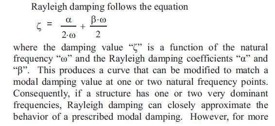
Rayleigh coefficient is a very interesting stuff. I took some time to investigate that and here are the findings. First, this is related to internal damping, and the damping ratio can be written as
Damping ratio = alpha /omega /2 + beta*omega /2
While the damping coefficient is = alpha * mass + beta * stiffness.
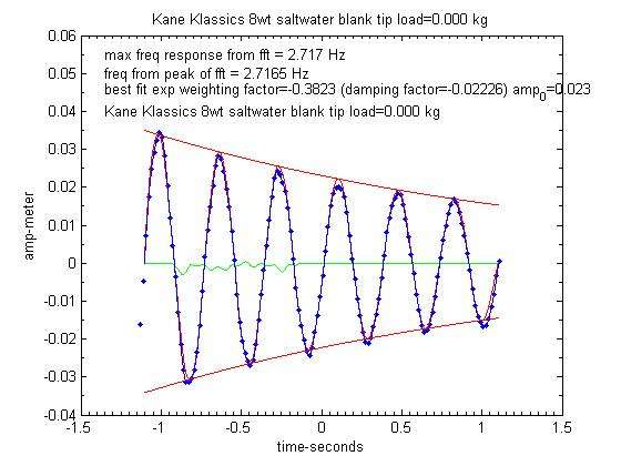
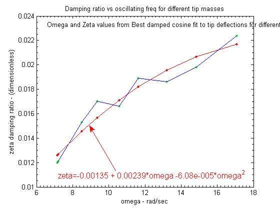
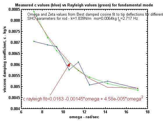
OK, so I played around with actual values, like for example what we get from the vibration damping of the first mode to try finding out alpha and beta values. The fact is that it is not straightforward and in practice this needs quite complex calculation for structures when you know their harmonics. You have got to use a number of harmonics to get a stable and unique solution for alpha and beta. Here is an illustration extracted from a publication, the “frequency” is in rad/sec, and the range corresponding to fishing rods is between 7 rad/s and 16 rad/s approximately.

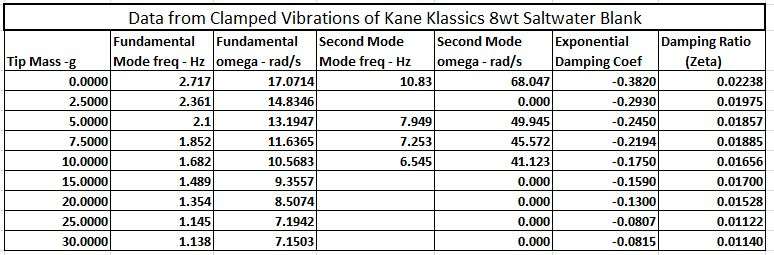
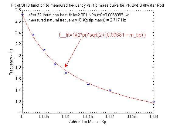
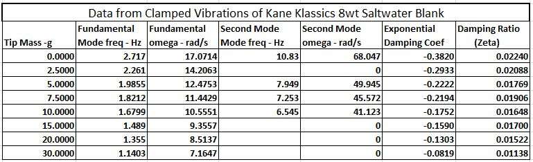
Nevertheless we can have a look at the possible ranges for alpha and beta. Let’s look at what I got for a typical 9 feet rod designed for a number 5 line:
If alpha = 0, beta = 0.0032
If alpha = 0.39, beta = 0.0016
If alpha = 0.78, beta =0
We may have rods sensitive to mass damping, others to stiffness damping, I cannot tell today but this opens a new area for investigation. Using the three first harmonics of a typical rod I can say the following:
In the first case, where stiffness damping is dominant, the damping of the third NF can be significant (damping ratio above 0.15), especially when the rod is not loaded (state 2). That makes me think about very fast rods when you just kick them a little bit in the shop they dampen quickly.
When mass damping prevails, this is just the opposite, higher NFs have less damping, very small indeed (0.004). Is this a source for wobbling?
In the intermediate situation, the stiffness character is dominating. So the question is: where are our rods?
If we look at the first harmonic, the values can range from 0.01 to 0.03 for the damping ratio without load. Still small, and when we take mass on board, let’s say 60 feet of line for some 20 grams, the maximum value is 0.78 *0.023 (mo is included) = 0.018 for the damping coefficient, which corresponds to something like 0.07 for the damping ratio: far from being critical (1).
The conclusion for me is that this approach is interesting for state 2 vibrations problems. Thanks a lot for bringing that on the table. For state 1, the drag effect is dominant, as we can see below.
I estimated the effect of air drag on the rod close to RSP, when tip speed is maximum. That can give a damping coefficient about 0.065 for a maximum tip speed of 25 m/s. Now if I imagine the mass being 13 grams and the stiffness 0.74 N/m, that would correspond to about 0.33 for the damping ratio at RSP. Pretty high. At the beginning of the cast the damping effect is nil (no speed), so it is not easy to define what could be an “average” damping ratio for a cast, since the SHO model needs one single value.
The conclusion of this is that when you witness a more pronounced damping effect as you cast a heavier line, it could well come from air drag since you use to cast such line at higher speed. At the very beginning of state 2, we have the same influence of air drag, and it disappears at MCF. After that we enter the material damping effect area again.
Merlin