I think that it is likely the amplitude of rod response which makes the system look like an unstable one. Aerodynamics experts see that with their “helicopter blades” eyes, but such amplitude is just the consequence of a transient motion, especially since there is no line on the rod.
I understand your intent but we are going to bump into the same issues in a discussion about Pauls rod. Please take a look at this reference, from which I have extracted the following quote:
The amplitude of a driven harmonic oscillator increases as the driving frequency approaches the natural frequency. In an un damped system, the amplitude will be infinite.
We have a damping ratio of 0.026. We will not go to an infinite response because the rod spring will saturate first. If the material is brittle we would have material failure first. The KK and fibre glass rods are more prone to large amplitudes because the material is compliant.
If you can find the time and the rod, could you run your zeta vs tip mass tests on a DH graphite rod? That would enlarge our understanding: DH rods do not seem to behave like SH during counterflex,
Merlin,
Sorry for the delay in doing this, but I think you will find the results interesting.
For the range of tip loads I used in this set of tests (0-50 grams) it appears the zeta damping ratio value is being dominated by the beta stiffening term in the Rayleigh damping equation.
Damping ratio = alpha /omega /2 + beta*omega /2
Now that I have crunched the data I wish that I had used some much larger tip masses to see where the knee of the Rayleigh damping curve might be for graphite rods. It would appear that the increase in the zeta damping ratio that is associated with the alpha coefficient and very small omega values does not enter into the picture until you use very large tip loads.
In doing the minimization to find an alpha value that would result in the least squares error between the expected value given in the above equation and the measured values for this data I found produced a negative value for the alpha coefficient. That is a physically impossible result. Thus I expect applying the much larger tip loads to produce small omega values of around 1 rad/sec would eventually give a positive alpha coefficient, if it did not break the rod in the process.
The way we are getting the alpha and beta coefficients assumes that the spring constant remains constant regardless of the mass sum value. Since k increases for the larger deflections associated with large tip loads that constant k value would no longer be true, so we may be pushing the Raleigh damping theory beyond its “linear” assumptions.
Here is the frequency vs tip mass curve for this 14 foot DH rod. This rod was purchased from the bargain cave at Cabellas so I expect it was made by a manufacturer in China.
You can see it had natural frequency of around 2 Hz, a spring constant of 1.62 N/m, and an effective mass of 10.4 grams.
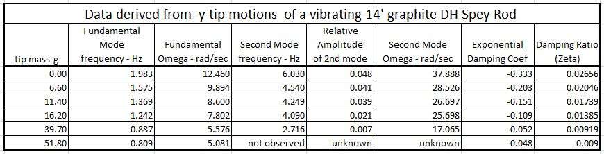
Here is the data summary of the frequency and zeta values that were measured for different tip loads on this rod.
It was easy to generate a second mode component with the initial deflections in this long rod, and their effects could be observed for tip loads as large as 40 grams. You can see the second mode frequency was about 3 times the fundamental mode in these tests. The zeta damping ratio had a nominal quadratic relationship to the added tip mass as shown below.
I wish that I had used larger masses to see if zeta would increase again as the Rayleigh damping theory predicts. However to get an oscillation frequency of 1 rad/sec the added tip mass would need to be around 1610 grams. I don’t know if this rod could support such a heavy tip mass and am very hesitant to find out. Even with a 60 gram tip mass the rod tip curled back significantly at the bottom of the swing, and I am afraid the blank might give up and break trying to swing a load that was 30 times larger.
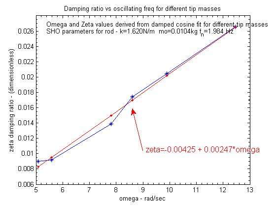
A plot of the measured zeta values as a function of the oscillation frequency produced a very linear relationship as shown below. The blue curve below is for the measured zeta values at different measured omega oscillation values. Aside from the flattening of the measured values observed for omega<5.5 rad/sec, the rest of the data had a very linear relationship with omega as predicted for the beta stiffening term.
That linear relationship is what you would expect for the beta stiffening term, although the pure stiffening term value would be expected to have zero intercept value at omega=0 vs the value of .00425 that was found for this data. That difference produces a non-physical alpha value when you fit the measured curve to find the alpha and beta coefficients that go with the Raleigh damping theory as shown below.
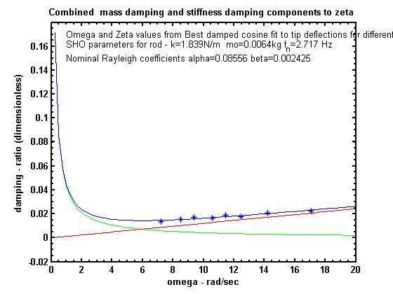
As before the red curve in this plot is for beta*omega /2 stiffening term where the best fit beta value was .0044 s. The green curve if for the alpha /omega /2 term and in this case has negative values since the best fit alpha term was -.0306 /s. For small values of omega that would result in negative zeta values which would cause the deflections to increase with time. That would violate the conservation of energy since there is no outside energy source in a clamped oscillation test.
The blue curve is the composite zeta vs omega curve expected from the Rayleigh theory that match up with the measured values that are shown with blue *. As noted before this test needs to be done with larger tip masses to see if the measured zeta values would start to increase again as expected for Rayleigh damping.
The KK data had more reasonable alpha and beta values as shown below. In that case the composite blue curve given by the Raleigh theory match up with the measured values quite well, and I expect a more reasonable match would also result for this DH rod had I applied larger and larger tip mass values.
However you can see the zeta values observed for the KK single handed rod were very close to the red stiffening values which indicates that the stiffening effects were the dominate source of the zeta variations for that set of omega values as well.
Gordy
"Flyfishing: 200 years of tradition unencumbered by progress." Ralph Cutter
Even if there is no dampening in the SHO model, the amplitude cannot go infinite because we just accelerate and decelerate once, and also because the casting arc is finite. The amplitude would go infinite if we could keep on repeating the input, which is not the case. Once we cast forward, the only possibity is to cast backward.
Under such condition (no damping), the maximum line speed achievable is equal to the maximum rigid rod speed multiplied by the squareroot of 2. This also means that the amplitude is finite (see the SHO thread).
Merlin
Fly rods are like women, they wont´play if they're maltreated.
Charles Ritz, A Flyfisher's Life
Really interesting. There is no contradiction with physics if alpha is negative. In fact, the condition to face this situation is:
zeta (for load m) < zeta (no load) / sqrt(1+ m/mo)
You have to play with the equations to find that. The damping coefficient will stay positive even if alpha is negative.
Apart from the mathematics, how can we conclude about rod lenght? With the long rod, beta is the double by comparison to the SH rod. If you compute the damping ratio for the second NF without load, both rods exhibit a value around 0.08 for zeta. So for the time being, I am still puzzled by the ability we have to dampen a DH rod. The video from Sakkari with his 18 feet rod does exhibit the second mode during the casting phase of the rod, but there is no vibration at the end. How does it compare with a soft SH rod? I cannot tell.
Maybe you will find the time and patience to do the same experience with a glass noodle. I cannot tell about what you will find in terms of zeta, I have to give more thinking to your experience.
Thanks again for this one, and do not try heavy loads, this is not needed.
Merlin
Fly rods are like women, they wont´play if they're maltreated.
Charles Ritz, A Flyfisher's Life
There is no contradiction with physics if alpha is negative. In fact, the condition to face this situation is:
zeta (for load m) < zeta (no load) / sqrt(1+ m/mo)
Merlin,
Does that mean that zeta will always continue to decrease (but maintain a positive value) as the tip load increases?
How does that square with the increase that you see in the composite zeta curve in the Rayleigh damping model for small values of omega?
Gordy
"Flyfishing: 200 years of tradition unencumbered by progress." Ralph Cutter
So for the time being, I am still puzzled by the ability we have to dampen a DH rod.
Merlin,
That makes two of us.
I am amazed by how much difference there is in the damping of a single hand rod when it is clamped vs when it is being held with one hand.
I thought I could measure the damping ratio with me holding onto the grip with one hand while my wife released the tip from some deflection point. I set up a white back ground that I use to make it easier to track the tip positions of the rod tip while it vibrated and then could crunch the resulting data the same way I do for a clamped rod.
Much to my surprise the response of the rod tip at the release time is much different than it is with a hard clamp. Unfortunately the tip was out of frame at the release point in this test since I was set up to track the oscillations that never happened. But you can see in the .gif below that the deflection in the rod goes up rather than down at the release point, and then the rod tip goes to a horizontal position as though it was over damped with little or no overshoot.
This just shows there is a big difference in the way the rod oscillates when it hand held (by a wimpy-wristed senior citizen) and when it is hard clamped.
Gordy
"Flyfishing: 200 years of tradition unencumbered by progress." Ralph Cutter
Whatever the rod is (KK or 14 feet), zeta goes down as load increases. It will remain positive even for the DH rod because the beta term is high in that case, but will reach some positive asymptotic value since the mass you can cast is limited.
Your experience holding the rod just illustrates how difficult it is to model a real damping action. For sure, most of the solution is on the caster's side, and it will take some time before we can understand how one can do that.
I found some scientific publication about the influence of length on damping ratios in beams of circular section. The way the rod is built (unidirectionnal fibers of angled fibers) appears to be the dominant factor. The length / diameter ratio has some effect on uniD beams, which tends to diminish and level as the length increases. Given the L/d ratio of our rods, we are in that region where the length should have no significant effect on damping ratio. If fibers are laid down at +/- 45 degrees, the damping ratio remains constant. I shall send you the document.
Merlin
Fly rods are like women, they wont´play if they're maltreated.
Charles Ritz, A Flyfisher's Life
Even if there is no dampening in the SHO model, the amplitude cannot go infinite because we just accelerate and decelerate once, and also because the casting arc is finite. The amplitude would go infinite if we could keep on repeating the input, which is not the case. Once we cast forward, the only possibity is to cast backward.
I'm fairly sure we have agreed with each other; that the rod is prevented from going to infinity by physical constraints.
However because it is divergent it satisfies the case for instability. The return to stability shows that it is dynamically unstable when driven. When you remove the drive it returns to statically stable.
I am not surprised that you are getting some anomalous low frequency readings in your zeta plots. My understanding is that the laboratory derived plots used a constant amplitude frequency. With the rod you cannot replicate that using mass alone and I suspect that acceleration becomes more dominant than frequency.
This reference may be of some use to you for modelling human mechanics and I wish you luck with it:
Whatever the rod is (KK or 14 feet), zeta goes down as load increases.
Merlin,
Does that mean the rise in the value of zeta for omega<4 in this Rayleigh damping plot for the KK rod would never happen in the real world?
If zeta always decreases with increasing tip load, what does the sharp rise in the composite zeta value (blue curve) for omega<2 rad/sec in the above plot represent?
If the f vs tip mass equation holds for large tip loads a tip load of around 450 grams would produce a loaded frequency of 2 rad/sec.
Gordy
"Flyfishing: 200 years of tradition unencumbered by progress." Ralph Cutter
I think there is a limitation in calculating the Rayleigh coefficient, which comes from the assumption that we can always model the loaded frequency with mo. In fact, this is an approximation which is valid up to some point. If you make a detailed analysis of a frequency curve, you can see that the equivalent mass and equivalent stiffness vary a little bit with load.
For large loads we shall enter a non linear domain in which the equivalent mass and especially stiffness will change significantly, and that does not make possible anymore the calculation of coefficients along the theoritical approach that we are using in a restricted domain.
Up to now, I have not found any publication about this difficulty.
Merlin
Fly rods are like women, they wont´play if they're maltreated.
Charles Ritz, A Flyfisher's Life
But you can see in the .gif below that the deflection in the rod goes up rather than down at the release point,
This is the same phenomena I suppose as casting from a straight rod where this tip is close to the wall. Shortly after you move forward the tip move back and strikes the wall.
This is the same phenomena I suppose as casting from a straight rod where this tip is close to the wall. Shortly after you move forward the tip move back and strikes the wall.
Paul,
As I noted I am puzzled by the rod tip motion after it is released from some static deflection point when it is held in the hand vs being hard clamped. The hard clamp has no energy absorption and can provide unlimited torque to offset the bending torque in the rod. Thus the tip always goes down towards its straight equilibrium point when it is released.
I think Merlin has explained that the kick back of the tip when it responds to a sudden angular acceleration of the rod butt is due to the second mode oscillation that is excited by that forcing function. In the slow motion video below you can see that as the butt section of the rod goes up as it responds to the sudden clockwise rotation of the rod, the tip goes down. That is the signature of a second mode vibration.
I will see if I can do the hand held release test again with a bigger field of view to see if something similar is going with second mode vibrations in that static deflection test.
Gordy
"Flyfishing: 200 years of tradition unencumbered by progress." Ralph Cutter
This corresponds to the linear solution and it is not a problem. I was speaking about non linear transient solutions for which I never saw a scientific publication.
Merlin
Fly rods are like women, they wont´play if they're maltreated.
Charles Ritz, A Flyfisher's Life
No problem Merlin, that's why my wife does not send me shopping. I assumed that you included nonhomogenous as non-linear but I understand the boundaries are blurred.
We could do with a scratch pad thread as I have a question about something we have discussed elsewhere. You mentioned keeping reels away from the hand and I have a build decision to make. Is a down lock seat technically better for reducing 2F modes?