It is so fast that the number of gs applied to the rod at the tip level is close to 58 gs, just enormous.
Merlin,
I am impressed that your model is getting deflections that are similar to the values shown in my video. I hope I can learn how to do your simulation, as you are predicting some serious inertial bending for large butt acceleration values.
How does the acceleration at the tip get to be that large? Is there a multiplying effect that comes from the spring in the rod?
Just doing a simple calculation for a stiff rod having a length of 2.54 meters, and an angular acceleration of the butt of 175 rad/s^2 the acceleration at the end of the rod would be 175*2.54=444 m/s^2 or 45 gs. That number would be reduced for a flexible rod since its cord length would be smaller. That 45 g value is impressive, but 58 gs is even more so.
Gordy
"Flyfishing: 200 years of tradition unencumbered by progress." Ralph Cutter
The number of gs is calculated from the ratio between the static deflection and the dynamic deflection in the SHO model.
Merlin,
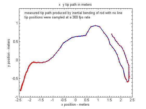
I computed the acceleration of the tip sqrt(a_x^2+a_y^2) along the white tip path shown in the video and was surprised by the magnitude.
Here is the tip path measured in that video. The red dots show how much the tip position changed every .0033 s.
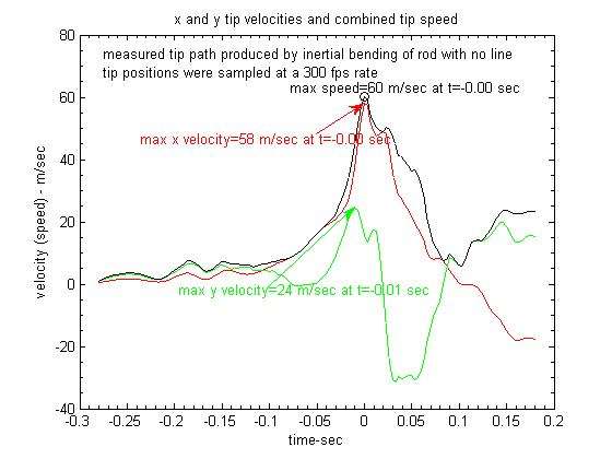
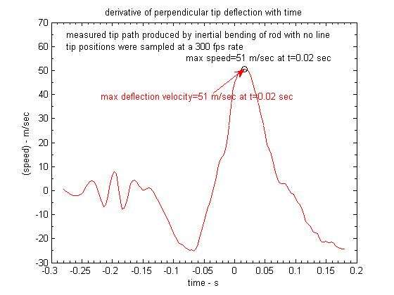
Taking the derivatives of those x and y positions with time you get this velocity profile.
As you noted in an earlier post the velocity near RSP is much higher than we see when casting a line and topped out at 60 m/s. I expect that reflects the higher angular accelerations you can apply to the rod without a line, and the fact that we are dealing with the unloaded frequency of the rod (f_n=2.7 Hz) as it unloads without a line.
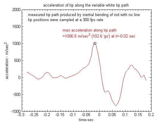
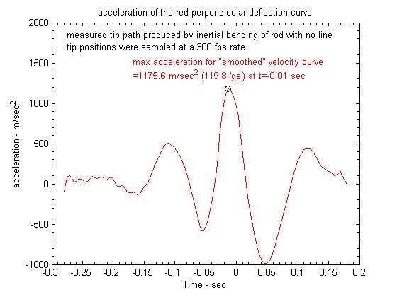
Taking the derivative of that speed curve you get the tip acceleration changes along that curved tip path. It really shoots up in the region of the hump that you see in the tip path as the rod straightens out at RSP1.
Check out the maximum value noted in that plot. It was around 100 gs!
Gordy
"Flyfishing: 200 years of tradition unencumbered by progress." Ralph Cutter
I checked the number of gs using the same methodology (relative rod speed and acceleration), and found 62 gs. Then I derated the model rod to have 3 Hz for NF1. The calculated deflection is now 1.57m. Quite good.
I shall check the casting model to see why I'm far below 100 gs, but you should check the NF1 for the rod if you can. 100 gs would need a fairly stiff rod to limit the deflection to 1.6 m.
Merlin
Fly rods are like women, they wont´play if they're maltreated.
Charles Ritz, A Flyfisher's Life
Gordy
we are comparing apples and pears
100 gs is absolute accel, but for the deflection we need the relative accel in the frame of the rod.
look for relative accel and you should come back to gs in the 50 range.
Merlin
Fly rods are like women, they wont´play if they're maltreated.
Charles Ritz, A Flyfisher's Life
I've witnessed the affects of tip acceleration of 120+ g's.
The caster had a substantial arm but, the values you are calculating are definitely attainable and of the magnitude I would expect to see. These values were obtained with a 10 gram load at the rod tip on a short 2 meter rod. The duration was very short.
If you get the rod acceleration against the load moving the opposite direction the acceleration goes through the roof briefly.
100 gs is absolute accel, but for the deflection we need the relative accel in the frame of the rod.
Merlin,
Do I get the acceleration in the frame of the rod by taking the derivative of the velocity difference between the actual rod tip and the tip of the broomstick?
Gordy
"Flyfishing: 200 years of tradition unencumbered by progress." Ralph Cutter
Do I get the acceleration in the frame of the rod by taking the derivative of the velocity difference between the actual rod tip and the tip of the broomstick?
and
Yes. Gordy
Merlin,
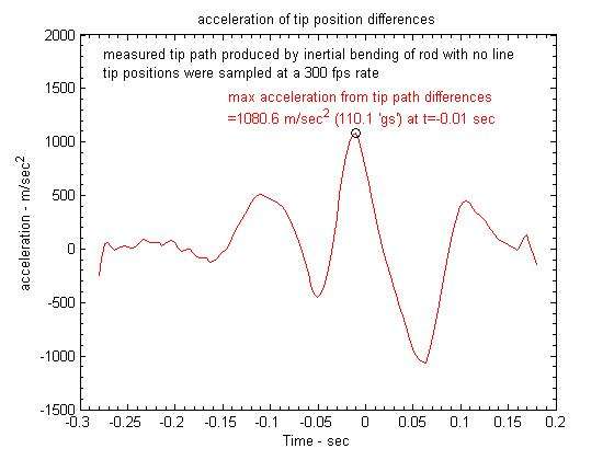
Here is the acceleration sqrt(a_x^2 + a_y^2) for that difference in the tip positions. The max of the second derivative of those x and y tip differences is still over 100 gs.
I also looked at the derivative of the red deflection curve vs. time and get this curve for the resulting one dimensional "spring" velocity (or speed). That did reduce the peak of the velocity to around 51 m/s which is very close to your prediction of 52 m/s.
Taking the derivative of that spring velocity gives this acceleration function. Peak value is still over 100 gs.
I don't know if the acceleration obtained from the deflection curve is closer to an apples to apples comparison with your model, but as Eugene indicated it appears you can get very large tip accelerations as the rod unloads from a big deflection of around 1.6 m. when large deceleration rates (-250 rad/sec^2 in this cast) are applied to stop the rotation of the rod.
Gordy
"Flyfishing: 200 years of tradition unencumbered by progress." Ralph Cutter
We can combine speeds but in the case of accelerations, the Coriolis effect is there due to the rotation. It is not easy to take it in account, acceleration vectors can be perpendicular so the estimates we get from derivating the relative speed are wrong I'm afraid.
I can't remember if this is the reason why I looked after the trick of comparing dynamic deflection with static deflection to get the number of gs.
The Coriolis effect may also explain why I cannot model correctly the tip path until now.
Merlin
Fly rods are like women, they wont´play if they're maltreated.
Charles Ritz, A Flyfisher's Life
A non-inertial rotating frame of reference with some rotational acceleration thrown in for good measure? I have some homework to do before I can even ask a reasonable question.
Gordy
"Flyfishing: 200 years of tradition unencumbered by progress." Ralph Cutter
For our 1D model, things are simple in that field, we can easily calculate the relative speed and acceleration, as we can do it (not so easily) for absolute speed and acceleration, with the knowledge of the displacement of the frame (translation). The way we transpose the situation to a fly rod is quite simple but it is an approximation.
When there is a rotation, as this is the case in real world for a 2D model, we have a rotating frame (the rod). For speeds, the equations do not change, but they do for acceleration because of the Coriolis effect.
Have some look at Wiki to see a simple illustration.
Merlin
Fly rods are like women, they wont´play if they're maltreated.
Charles Ritz, A Flyfisher's Life
As the rod is at maximum bend, the relative speed is nil in the rod frame, so the Coriolis effect is nil. I find 114 gs in that case for my model. The problem is that it may not represent the acceleration creating the bend. Otherwise it is impossible to find 1.6 m, you get a much higher value with 114 gs by comparison to something like 60 gs. I have to turn that in my head several times before understanding where the confusion is.
Merlin
Fly rods are like women, they wont´play if they're maltreated.
Charles Ritz, A Flyfisher's Life
I'm pretty sure that the wrist is the source of the "wave" in your cast, and I am impatient to see what you can get from the analysis.
Merlin,
I think the place for discussing the inertial bending more rightly belongs in this thread so I will put the data you were looking for below.
I was working to get the draggable digitize function in Matlab modified so it would display the video image on a bigger scale and allow for putting the broomstick position on the frame to help find the rod tip position. That was the reason it took so long to compute the angular joint velocity data for the inertial bending video.
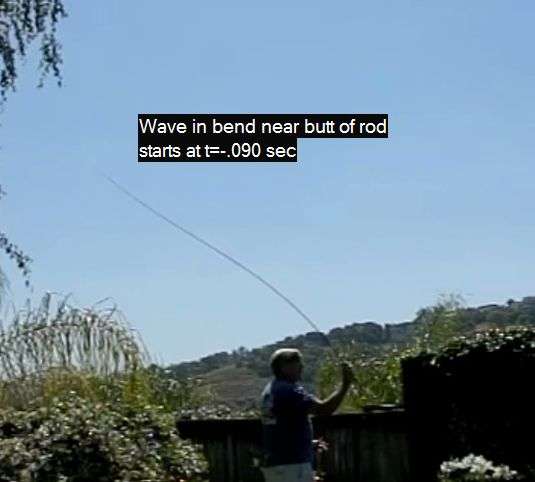
As you conjectured, I think the resulting data shows the "wave" you see start to run up the rod in the video below is initiated by an increase in the wrist rotation velocity.
Here is a frame grab that is around the point you start to see that "wave" running up the rod. The time of that frame (#539) was 90 ms before the RSP1 frame (#566).
Note that the bendform of the rod at that time point had a strong second mode signature.
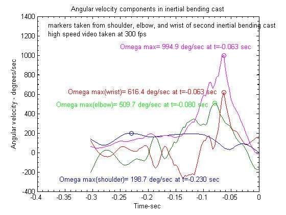
Here is a plot of the angular velocity of the different joints in that cast. This is a rather jumbled plot but you can see the wrist velocity (red curve) is starting to increase at around t=-.11 sec in that plot.
It is starting from a negative value because I had opened up the wrist angle prior to that point. At any rate it appears to start to take off before the next big change in the elbow velocity increase and its acceleration input at that point was most likely the source of the increase in the rod bend at t=-.09 sec.
Gordy
"Flyfishing: 200 years of tradition unencumbered by progress." Ralph Cutter
Impulse at – 110 ms / - 113 ms: it likely induces the second NF which should be close to 10 Hz, it is likely it appears at – 15 ms (small plateau lasting some 10 ms) and + 83 ms (change in direction in tip motion between 80 ms and 87 ms).
From the start of the impulse up to -53 ms, the tip trajectory is a plateau indicating there is a wave coming from the butt which “overloads” the rod, driving down the trajectory from the trend (climbing tip). - 53 ms corresponds to maximum deflection.
The timing from impulse = 110 – 53 = 57 ms for the time needed to travel from butt to tip for that wave, is compatible with calculations corresponding to an “auto similar” wave for a very fast rod (55 ms).
From – 53 ms to RSP1, there is a reflection of the wave causing strong tip bend which drives the tip up, adding extra unloading contribution to the rod.
From 0 to 35 ms /40 ms, the counter flex is disturbed by the pullback which takes place at this timing. Again the rod is driven from the butt with some extra bend; the trajectory goes downwards after the extra bending wave has reflected on the grip at RSP.
MCF occurs at 67 ms indicating a first NF about 3.7 Hz minimum. This is compatible with NF2 at 10 Hz.
Coming back from MCF is severely damped, with a damping ration around 0.74; the extra wave has reflected at the tip again and the trajectory goes up, higher that during RSP1 to MCF. RSP 2 is achieved 166 ms after RSP1.
Max rebound takes place at 92 ms and the tip trajectory seems slightly influenced by the phenomenon.
If I mimic the cast with the explicit model, I find a maximum speed of 64 m/s, slightly above the record (60 m/s), after tuning the damping ratios to get max deflection and counter flex values. The maximum number of gs is 88. This modeling is much closer than the first attempt I did some time ago.
What type of rod were you using?
Merlin
Fly rods are like women, they wont´play if they're maltreated.
Charles Ritz, A Flyfisher's Life