PLEASE NOTE: This is the Archived Sexyloops Board from years 2004-2013.
Our active community is here: https://www.sexyloops.co.uk/theboard/

Inertial Bending - How much does it add to rod bend?

gordonjudd
IB3 Member Level 1
Posts: 2214
Joined: Mon Jul 10, 2006 12:14 am
Location: California
Contact:

Post by gordonjudd »

What type of rod were you using?

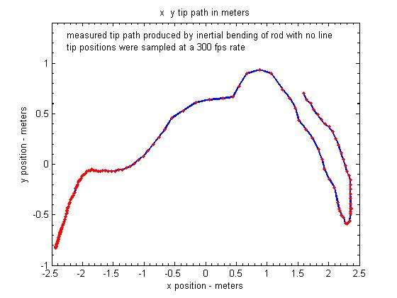
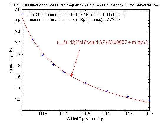
It was a KK 8 wt saltwater rod.

I did not do the freq vs tip mass measurement for that orignial rod so I do not have measured values for it other than knowing it had a NF of around 2.7 Hz.

I broke the tip of the original rod in an ill-fated attempt to measure the twisting torque it had due to its spine. Its replacement blank had the k and mo values noted below.
Image

Gordy
"Flyfishing: 200 years of tradition unencumbered by progress." Ralph Cutter
User avatar
Merlin
IB3 Member Level 1
Posts: 798
Joined: Sat Mar 27, 2010 3:30 pm
Contact:

Post by Merlin »

Thanks Gordy

I have to rework the model, using the numerical one. The pullback and the potential effect of the "wave" could disturb the speed of recovery

Merlin
Fly rods are like women, they wont´play if they're maltreated.
Charles Ritz, A Flyfisher's Life
User avatar
Merlin
IB3 Member Level 1
Posts: 798
Joined: Sat Mar 27, 2010 3:30 pm
Contact:

Post by Merlin »

Hi Gordy

The results from the numerical model:

Image

Image

Image

Seems quite fair now. I used 2.7 Hz for the rod, and tuned the damping values to come close to your record. Timings look OK apart for max speed which occurs before RSP, maybe because the rotation speed profile is a bit sharp by comparison to reality.

Merlin
Fly rods are like women, they wont´play if they're maltreated.
Charles Ritz, A Flyfisher's Life
gordonjudd
IB3 Member Level 1
Posts: 2214
Joined: Mon Jul 10, 2006 12:14 am
Location: California
Contact:

Post by gordonjudd »

Timings look OK apart for max speed which occurs before RSP,

Merlin,
I think you are homing in on matching the expectations of the model with the measured data.

Do you have the effects of the second mode included in your model?

I think it is the unloading of the second mode that causes the hump in the actual tip path around RSP1. That quick "flip" of the tip gives an added increase in the tip velocity since the second mode has a faster frequency, and there is not much moving mass in that mode. You can discern that effect in the white tip path in the video and the plot of the tip path below.
Image

Image

That is a much more wobbly tip path than the one we see with a line, so I am wondering if the relative amplitude of the second mode is much smaller when there is a tip mass.

As you mentioned the vibration node will move further up the tip with an added tip mass, so that will also reduce the omega*r velocity for the tip since the r component will be much smaller with a tip mass.

Gordy
"Flyfishing: 200 years of tradition unencumbered by progress." Ralph Cutter
User avatar
Merlin
IB3 Member Level 1
Posts: 798
Joined: Sat Mar 27, 2010 3:30 pm
Contact:

Post by Merlin »

Gordy

No, I can't model the higher frequencies, it is a 1 D model, you know.

It could be an effect of NF2, but the problem is to identify the frequency value. With a first NF at 2.7 Hz, it would be around 8.6 Hz.

More analysis work to do, I'm afraid. Incidentally, the extra bend in the rod could at the same time correspond to a flexural wave and would be caused by the Coriolis effect. Chicken and egg, likely.

Merlin
Fly rods are like women, they wont´play if they're maltreated.
Charles Ritz, A Flyfisher's Life
Locked

Who is online

Users browsing this forum: No registered users and 0 guests