Vince,
OK lets agree that there are no voids in a fly line, and assume that the fly line is reasonably uniform along its length and devoid of any pits on its surface. I think that is a pretty safe real world assumption.
As long as any possible small air bubbles in the plastic were evenly distributed they would still give an average value for the volume mass density as James has explained.
Linear mass density is not the same as mass unless the fly line is solid as I have just shown you.
Voids or no voids I would agree (who wouldn't) that the linear mass density of a line is different that its mass. Even a lead core line with a plastic coating is going to have some nominal average rho_l value that would be determined by the density and areas of the core and the coating.
In any case, to get the mass you would need to know the length of line involved. Same for a viscous fluid going through a pipe, so I do not know what being solid would have to do with that obvious difference between mass and linear mass density.
delta_p=rho_l*(v_fly/2).^2
I am glad you agree with Hendry, but to use it you would have to know what rho_l would be for a given line. For the line above how would you get the linear mass density for a floating line having a density of 850 kg/m^3 and a diameter of 1.3 mm. Matlab gives something around 1.128 g/meter.
Understanding the importance that the linear mass density has in determining the positive acceleration on the loop is the key to understanding why the taper in a line tends to slow down the velocity of the fly not speed it up. I hope that now makes sense to you.
Gordy
"Flyfishing: 200 years of tradition unencumbered by progress." Ralph Cutter
Thank you for a reasoned reply. With this explanation I can point to what is causing me angst.
Same for a viscous fluid going through a pipe, so I do not know what being solid would have to do with that obvious difference between mass and linear mass density.
It is a matter of accurate technical definition of terms. It we take PTFE for example at a mass density of 2.15 g/cc:
Lets take 1cc of PTFE and mould it into a solid sphere. The sphere density is what James called composite density. We get the following detail:
Mass Density 2.15 g/cc
Volume 1.00 g/cc
Radius 0.56 cm
Area 3.55 cm^2
Sphere Density 2.15 g/cc
If I now triple the volume of the sphere(making it hollow or voided) but use the same amount of PTFE, I get:
Mass Density 2.15g/cc
Volume 3.00g/cc
Radius 0.98cm
Area 6.14 cm^2
Sphere Density 0.72g/cc
The mass density and mass of both spheres are the same, so for an applied force they would have the same momentum. The larger volume sphere turned from a sinker into a floater and the drag increases with increase in surface area.
As you could see from the data sheet, mass density is a fixed value of a material that implies a range of other properties such as tensile strength and elongation values. Object or composite density varies with construction.
For the line above how would you get the linear mass density for a floating line having a density of 850 kg/m^3 and a diameter of 1.3 mm.
delta_p=rho_l*(v_fly/2).^2
This is what set me off on this path, I cannot see diameter in the delta momentum equation so cannot see how the DT line mass is being varied. As I mentioned in a previous post, given that mass density is a fixed value, it appears that the formula only applies to a level taper line.
I'll ask this question separately because it is where I wanted to get to:
Understanding the importance that the linear mass density has in determining the positive acceleration on the loop is the key to understanding why the taper in a line tends to slow down the velocity of the fly not speed it up.
Looking back at the graphs the only deceleration I can see is around the 39/40m point of the graph, regardless of the starting velocity. What is causing 3 casts with a different momentum to come to a halt at the same time?
The mass density and mass of both spheres are the same, so for an applied force they would have the same momentum.
Vince,
Do your calculations again for the cylindrical shape of a 1 meter length of fly line to come up with the comparative mass and linear mass density values. It is the rho_l that is used in Hendry's equation, not the volume mass density, so I don't understand why you chose a spherical shape in your example.
Floating lines typically have a volume mass density of around .85 g/cm^3 so they they will float. Bruce Richard's says in his book:
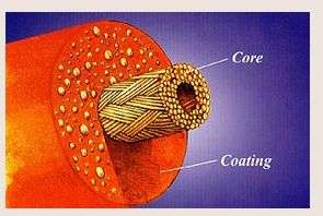
As mentioned earlier floating fly line coatings are lighter than water, usually because some low-density filler is part of the coating formulation.
For a 7wt line he says the core diameter is .025" and the coating diameter is .055" that would give a line diameter around 2 mm as shown below:
You can the micro balloons in this cross section that are used to reduce the overall line density and make it float.
Thus to get values that make sense for a floating line you might want to use the actual .85 g/cm^3 value for your material density since fly lines are not composed of pure PTFE. They would sink like a stone, and break easily if they were.
What is causing 3 casts with a different momentum to come to a halt at the same time?
Take a look at the scales on Lingard's graph. The x-axis is the fly displacement distance from its initial starting position 20 meters behind the caster. If you were reading distance and thinking time, it is no wonder why you do not understand this.
They all end at at the same distance since the line length (20 meters) was the same in all cases.
There are some plots of velocity vs time here that compares the velocity for different drag conditions using Lingard's analysis as a function of time. That graph may make more sense to you since it shows the end of the line is reached sooner when the velocity is higher.
Gordy
"Flyfishing: 200 years of tradition unencumbered by progress." Ralph Cutter
Thank you for putting the effort into researching that post.
I chose a sphere due to time constraints, I was doing the calculation at the same time as working. It appears to me that you can now see why there is no unconditional link between mass density and drag. So we are in agreement that rho however you define it is a fixed figure.
So how does Lindgard get a delta p from the following equation?
delta_p=rho_l*(v_fly/2).^2
If you were reading distance and thinking time, it is no wonder why you do not understand this.
Perhaps my question was not clear. You have stated a couple of times that:
Understanding the importance that the linear mass density has in determining the positive acceleration on the loop is the key to understanding why the taper in a line tends to slow down the velocity of the fly not speed it up.
Where is this happening, none of the DT traces reduce in velocity until the end of the line is reached?
So we are in agreement that rho however you define it is a fixed figure.
and
So how does Lindgard get a delta p from the following equation?
delta_p=rho_l*(v_fly/2).^2
Vince,
That question would seem to imply that you do not realize the difference between rho (the volume mass density that is 850 kg/m^3 for a floating line) and rho_l (the linear mass density that has the dimensions of kg/m as it is used in Hendry's equation).
For a given volume mass density, rho, the linear mass density of the line, rho_l, will vary as the square of its radius. That is why I asked you to calculate it for different line diameters. Then you would understand that a thin 2 wt line will have a linear mass density that is much different than a thicker six weight line.
That linear mass density difference explains Merlin's observation that:
A smaller line size will decelerate instead of flying at constant velocity (at the beginning), and this is the reverse situation for a higher line size (accelerate).
In practice, I find that this limit is around a number four line with my rods (on the high speed side and tip action side). You know you cannot expect a number three to behave like a number six in terms of distance with a given loop size.
I thought you understood this when you noted,
Thank you for your explanation. I am comfortable with the momentum/drag effects
but I do not see how if you assumed Hendry was using the volume mass density rho value in his dp/dt equation.
Also I hope you realize it is the change in the momentum of the mass in the top leg that determines the acceleration value. Thus the tug of war is not going on between momentum and drag as implied in your statement.
It is the balance determined by the momentum change and drag in the fly leg that determines if the loop accelerates or decelerates as it propagates.
Gordy
"Flyfishing: 200 years of tradition unencumbered by progress." Ralph Cutter
Hey guys,
finally I agree with Lasse ticking will not happen per se on longest carries.
I went out casting the GT140 directly over water. And to my surprise I did not tick.
I simply was mistaking a sound that comes by my fluff running thru the dangle as a "ticking-sound". It seems to happen exactly when the fluff makes the biggest change of direction. The very next moment the fluff runs upwards (following the dangle) like hell.
Seeing the line end/leader "jumping" upwards like hell and hearing that sound I thought I was ticking. And so thought others after pointing that out to them, too.
But I was wrong.
The sound happens while casting over water without hitting at all. So it has to come just from the change in direction.
Now am wonedering if the fluff breaks the sound barrier here (in the middle of the cast.
Actually I think it does at least on longest carries. Cause the sound kind of gets loud then.
Bernd,
I think the drag on the fluff will be high enough to keep it from breaking the sound barrier.
What is the nature of the sound the fluff is making? The sharp "crack" that you get when the end of a fly-less leader breaks the sound barrier is pretty distinctive.
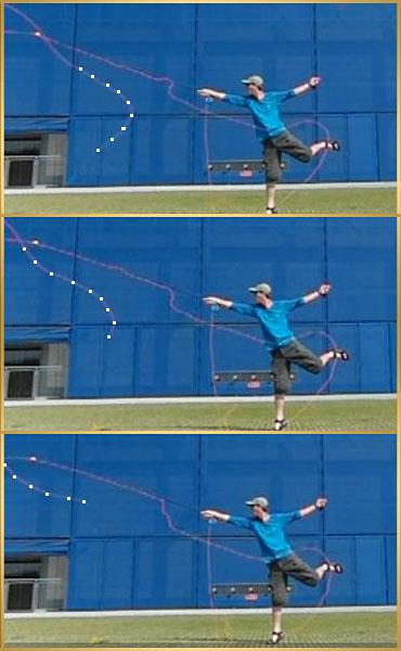
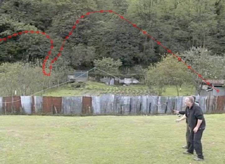
If you can see it, try marking the position of the fly in Lasse's video on a frame by frame basis. I don't think you will see a sudden increase in the distance between those tracking points as the fly goes through the dangle path.
That was the case in tracking the position of the fly in Aitor's early tail video on a frame by frame basis below.
Gordy
"Flyfishing: 200 years of tradition unencumbered by progress." Ralph Cutter
This is what set me off on this path, I cannot see diameter in the delta momentum equation so cannot see how the DT line mass is being varied.
Vince,
How do you calculate the linear mass density (rho_l) at a given point in a fly line?
It is simply the volume mass density times the cross-section area. Thus the impact of different diameters shows up in Hendry's equation because they will produce different rho_l values assuming both lines have the same volume mass density of 850 kg/m^3. If you double the diameter, the linear mass density (kg/m) will increase by a factor of four.
There is also a m*dv/dt term for the overall momentum change in the line, but it will be near zero when the velocity changes are small.
Gordy
"Flyfishing: 200 years of tradition unencumbered by progress." Ralph Cutter
Hi Gordy,
pretty hard to describe the sound . It differs with the length of leader, with the size of fluff, with the length of line (line velocity).
At least it is loud enough that I can hear it pretty clear. Kind of remembers me to the sound I can create by looping a towel. Just less intensive.
I was rereading the whole thread. In Tom's video we could see that if the rod-leg has the same (negative) acceleration than the fly-leg has (positive), the loop will not move but kind of be "frozen".
If I understand that correct it should mean the fly leg should not be accelerated by pull back?
But when using pull back in false casting I feel a much better tension at the end of unrolling. This tension feels like someone is trying to pull the rod out of my hand.
Where exactly does that come from?
Is it that my loop gets smaller and therefore velocity of the fly-leg increases AND less energy will be lost during unrolling?
I am not disagreeing with you on this point but radius does not appear in here:
delta_p=rho_l*(v_fly/2).^2
So how does this formula give delta p?
Additionally the radius will change the drag value, so your statement should have read:
It is the balance determined by the momentum change and changing drag force in the fly leg that determines if the loop accelerates or decelerates as it propagates.
Vince
I have been thinking about this and believe I can see the problem:
How do you calculate the linear mass density (rho_l) at a given point in a fly line?
It is simply the volume mass density times the cross-section area.
rho_l (the linear mass density that has the dimensions of kg/m as it is used in Hendry's equation).
For a given volume mass density, rho, the linear mass density of the line, rho_l, will vary as the square of its radius.
In all definitions of rho_l that I have seen, it uses physical properties such as volume mass and radius that describe a 3D object such as a fly line to create a 1D object for the purposes of modelling. I think at this point we are saying the same thing.
The kg/m definition does not care if the string is a hair or an anchor rope; mathematically it is treated the same. It does not define whether the line will float or sink and cannot be used to calculate drag without reverse engineering the radius value back out. Consequently, it is being used in the models to calculate momentum by describing the mass distribution along the line.
Generally, the value is of rho_l constant along the length. On the occasions where the linear mass density value is not not homogeneous, it is usual to provide the co-ordinates of the point you are referring to or to define how you are describing the distribution of mass. This is where I think we differ, I cannot see from what you have shown so far how the mass is being distributed across the 1D line. It is essential to know how this is being described for the DT because of how variation in taper effects the velocity of the fly.
Hi everyone,
I finally tried to go thru Gorielie's and MCMillen's great work on whip physics.
I got lost somewhere inbetween all these formulas .
He wrote:
"The main effect seems to be the tapering in the rod, which increases the maximal speed nonlinearly. Thus, the main key in successful whip cracking seems to be in the design of an efficient elastic tapered whip as both whip artists and craftspeople will tell you."
If I watch this slomo I cannot see any serious increase in speed of the cracker-leg during unrolling.
So to me it SEEMS that I am not understanding his simple statement yet.
Wouldn't tapering slow down the unrolling???
The more tapering there is the less energy will be left short before the cracker?
I thought the tapering would just help to be able to use the butt section as a flexible leaver to produce velocity very effectively without having to add too much force.