
Merlin - absolutely right! You don't need to be at the limit of compression you need to be outside the zone where the rod acts as the ideal, i.e. equivalent to infinite compressiblity. :p When you exceed that zone then the rod needs to buckle and wrinkle on the compressed side in order for further bending to occur.Merlin wrote:Walter
(d) and (g) look like micro/local buckling (reknowned to occur before buckling). It is again a failure by compression, but I am not sure that you need to be at the limit of compression to observe it.
PLEASE NOTE: This is the Archived Sexyloops Board from years 2004-2013.
Our active community is here: https://www.sexyloops.co.uk/theboard/
Our active community is here: https://www.sexyloops.co.uk/theboard/
Effect of taper on spring nonlinearity - How does taper impact the k3/k1 ratio?
-
Hal Jordan

- IB3 Member Level 1
- Posts: 604
- Joined: Thu May 05, 2011 1:17 am
- Contact:
-
Eugene Moore
- IB3 Member Level 1
- Posts: 93
- Joined: Wed Jul 06, 2011 1:27 am
- Location: Missouri
- Contact:
Gordon,
The failure was a delamination ( good material break )
The load was approx 200 in lbs well within 2 handed capabilities.
This was a previously broken blank about 18 inches long.
The butt was clamped and load applied at the end and measured as it was increased.
Radius at failure was approx 1300 inches. About 2 inch deflection.
Failure location was 4 inches from the butt. Measuremets were taken 8 inches from the butt.
Vince,
The reason The deflection is at the butt is the open area of the blank. As open area diminishes at the tip the ovalization is not allowed to progress. We're looking at a thick walled beam.
Difference between tension and compression is lower due to the decreased ratio between inside and outside of the arc versus the neutral axis of the blank.
Please everbody. This is a voluntary forum. It's rude to dress an individual down publicly. Praise should be done openly.
Stubborn, Hard-headed are all signs of scientific thinking. If you have an idea you deserve the right to dig your heels in and defend it. My dealing with all individuals here has been encouraging. I may not understand you commitment but should still accept it as plausible. Since when has science ever been democratic or achieved a consesus of vote. If that was the case the earth would be the center of the universe and flat.
Sorry for preaching.
Eugene Moore
-
Hal Jordan
- IB3 Member Level 1
- Posts: 604
- Joined: Thu May 05, 2011 1:17 am
- Contact:
-
Paul Arden

- Fly God 2010
- Posts: 23925
- Joined: Sat Jul 26, 2003 10:35 am
- Location: Travelling
- Contact:
-
Hal Jordan
- IB3 Member Level 1
- Posts: 604
- Joined: Thu May 05, 2011 1:17 am
- Contact:
Isn't it obvious that way? :p
I'll do a picture version when I get a chance.
Nope - doesn't work like that....[/color]
I'll do a picture version when I get a chance.
Code: Select all
ε = ((ρ-x)dΘ - ρdθ/ρdθ = (ρdΘ-xdΘ - ρdθ/ρdθ -
Paul Arden
- Fly God 2010
- Posts: 23925
- Joined: Sat Jul 26, 2003 10:35 am
- Location: Travelling
- Contact:
Eugene
I'm not 100% sure that we are on the same page and that I understand your statement. I think that you are saying that wall thickness and susceptibility to Brazier effects is defined only by inner/outer radii. Two weeks ago I would have agreed with you.
However, it is a simplified view and is why the D/t ratio cannot be used as an absolute guide. If it were an absolute the bending behaviour of a steel and rubber tube would be the same if they had the same diameter and wall thickness.
I dislike saying that fishing rod is a special case but in this instance there are some exceptions to the D/t rule of thumb because the rods flexural strength varies along with the taper and it is these variations in flexural strength that Tatting was addressing in chapter 6 of his thesis and where I took the quote:
Tattings thesis is here:
http://scholar.lib.vt.edu/theses....sis.pdf
I suspect that the butt of the rod is behaving in accordance with the classical solution and that is what you are measuring. However, I also believe that the top of the rod is exhibiting "drastic Brazier nonlinearity" because of the reduction in flexural strength relative to the butt. There is certainly some strong circumstantial evidence as a result of observation (and backed up by Merlins model) that indicates the smallest bend radii in normal use of a rod occurs about 75-80% of its length.
Even if you use the strain figures for the fibres (which I think are overstated compared to the actual construction matrix), the strain values in the small radii bending region are low relative to the butt, so what is allowing the rod to bend so drastically?
The other thing I think we tend to forget when we are looking at numbers is that most rods are multi-part and that elongation of the fibre is not for a single fibre running from butt to tip. It is possible to achieve the small radii bends just using the top section of a 4 piece rod.
I'd assumed that you were measuring ovalisation at the butt because it would be sufficiently large to be measurable. According to CTS we would be looking for about .008mm ovalisation in the top section of the rod which is beyond my shed technology. However, I anticipate that we will find the alpha figure (percentage reduction) for ovalisation will be larger in the top of the rod than the butt based on Tattings calculations.
Vince
I'm not 100% sure that we are on the same page and that I understand your statement. I think that you are saying that wall thickness and susceptibility to Brazier effects is defined only by inner/outer radii. Two weeks ago I would have agreed with you.
However, it is a simplified view and is why the D/t ratio cannot be used as an absolute guide. If it were an absolute the bending behaviour of a steel and rubber tube would be the same if they had the same diameter and wall thickness.
I dislike saying that fishing rod is a special case but in this instance there are some exceptions to the D/t rule of thumb because the rods flexural strength varies along with the taper and it is these variations in flexural strength that Tatting was addressing in chapter 6 of his thesis and where I took the quote:
Therefore, for a given material system, low values of l (which produce very little Brazier effect) are generated by short and thin cylinders, and buckle according to the classical solution. Longer and thicker cylinders, which are more easily construed as “tubes”, undergo drastic Brazier nonlinearity before buckling occur
Tattings thesis is here:
http://scholar.lib.vt.edu/theses....sis.pdf
I suspect that the butt of the rod is behaving in accordance with the classical solution and that is what you are measuring. However, I also believe that the top of the rod is exhibiting "drastic Brazier nonlinearity" because of the reduction in flexural strength relative to the butt. There is certainly some strong circumstantial evidence as a result of observation (and backed up by Merlins model) that indicates the smallest bend radii in normal use of a rod occurs about 75-80% of its length.
Even if you use the strain figures for the fibres (which I think are overstated compared to the actual construction matrix), the strain values in the small radii bending region are low relative to the butt, so what is allowing the rod to bend so drastically?
The other thing I think we tend to forget when we are looking at numbers is that most rods are multi-part and that elongation of the fibre is not for a single fibre running from butt to tip. It is possible to achieve the small radii bends just using the top section of a 4 piece rod.
I'd assumed that you were measuring ovalisation at the butt because it would be sufficiently large to be measurable. According to CTS we would be looking for about .008mm ovalisation in the top section of the rod which is beyond my shed technology. However, I anticipate that we will find the alpha figure (percentage reduction) for ovalisation will be larger in the top of the rod than the butt based on Tattings calculations.
Vince
-
Eugene Moore
- IB3 Member Level 1
- Posts: 93
- Joined: Wed Jul 06, 2011 1:27 am
- Location: Missouri
- Contact:
Vince,
I believe the Brazier effect, like deflection, takes place over the entire deflected length of the blank.
The the amount of the effect is in the opposite direction of the deflection caused by load.
As load is applied tip deflection is greatest and butt least. The cumulative effect is what we observe.
The Brazier effect isn't propeled by the load but rather the torque applied over the blank length. This is least at the tip and highest at the butt. The butt ovality is small but it's effect is seen as great on the accumulated deflection.
I've worked on and off at the creation of a math model to describe rod deflection behavior. The model calculates a linear taper blank and also a measured taper blank at the same load for comparison. The results are then compared to an actual rod. Currently the measured taper model compares favorably with the actual rod, but falls short on the total deflection at higher loads. This I feel is the result of the Brazier effect in the butt section as the tip is a very good match. Small changes in the butt deflection have a large effect at the measured tip deflection.
I'm looking for a better model.
By the way, in reference to this original thread, the effect of rod taper on the actual rod versus a linear taper math model is in the order of 20% stiffer for the actual rod. The linear taper shows much more deflection in the butt than the actual or my tapered model show.
My end result would be the addition of dynamic loads to a model that accurately portrays static loads.
I feel the dynamic aspect of the taper distribution is why the expensive rod "feels" so much better than the cheap rod
Just my humble beliefs when attempting to explain the difference between a $30 blank and a $400 blank.
Eugene Moore
Hi Eugene
I agree that the the Brazier effect takes place throughout the rod and its a logical extension that ovalisation will also occur along the full length to a greater or lesser degree. I suggested looking at where the bend radius was smallest as being the most likely place that the ovalisation ratio would be highest. But until I worked my way through Tatting I did not see how that would work.
I did find a reference somewhere that mentioned that the difference in accuracy between the engineers beam and Brazier models was single digit in percentage terms but I did not quote it in the thread as I felt it was a bit of a sweeping statement. The more I read into it, the greater I feel the effect of orthropy that Walter raised has on the results and that would be a goat to incorporate into a model as the construction data is not readily available. I believe Merlin has looked at transversal modulus and found it difficult. This may defeat us but the Earth will still be round.
Vince
-
gordonjudd
- IB3 Member Level 1
- Posts: 2214
- Joined: Mon Jul 10, 2006 12:14 am
- Location: California
- Contact:
The load was approx 200 in lbs well within 2 handed capabilities.
This was a previously broken blank about 18 inches long.
Eugene,
How much of that 18' section was embedded in the clamp?
Does that imply the tip force was around 200/18=11.1 lbf (50 N)? For a 2in (.0508 m) deflection that gives a spring constant of 973 N/m. Since the spring constant is equal to 3*EI/l^3 that would say EI=973*l^3/3=30.9 N-m^2.
If the outside radius was .0033m and the inside radius was .0028m I calculate a Young's modulus of 651 GPa and a stiffness factor (B=E*I) of 30.9 N-m^2. That would seem to say your outside radius was greater than .0033 m, as the effective Young's modulus for most graphite rods is around 100 Gpa.
Radius at failure was approx 1300 inches.
A 5mm outside radius would give a radius of around .19 inches. If the radius value was equal to .13 in that would give an outside radius of 3.3 mm. That seems small for a butt section.
What was the wall thickness where it broke?
Thanks for giving more details about that experiment. Do you have any estimate for the strain in that section when it failed?
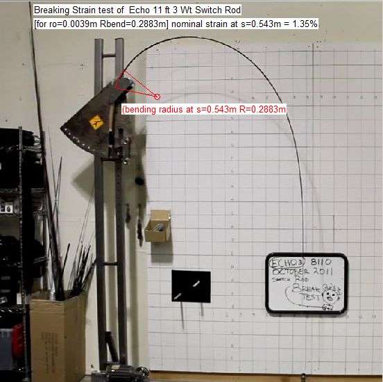
In the break test of an Echo 8wt 11 foot switch rod shown here the strain in the area that failed was around 1.4% just before it snapped assuming the outside radius at the failure point was around 3.9mm.
Gordy
"Flyfishing: 200 years of tradition unencumbered by progress." Ralph Cutter
-
Hal Jordan
- IB3 Member Level 1
- Posts: 604
- Joined: Thu May 05, 2011 1:17 am
- Contact:
VGB, Eugene,
I'm wondering if rods are best modeled as bilayer and trilayer systems. That could be part of the difference between the $50 blank and the $300 blank. The failure modes noted by Rajeff would also be consistent in that regard. In fact, given that Tim was eyeballing things he probably missed the fact the the point fracture could actually take the form of a cone fracture or a deformation of the substrate which would mean there would be at least 3 distinct failure modes.
Eugene - your observation about small deflections at the butt resulting in large changes at the measured tip deflection is interesting. I recall Merlin saying he has been using an FEA with 50 elements and comparing the results to another model. It would be interesting to see how an increase in the number of elements would affect the comparison.
I had an off-line chat with Merlin about the FEA. I thought that I could do some validation of the model based on the ZXL blank that I am about to start building. However, I could not get the tip diameter below 2.8 mm without convergence problems appearing in the model, the ZXL is about 1.2mm at the tip. This does not invalidate the model for trend type information but I would be cautious of declaring absolute values as a result because Parkinson indicates that the rate of taper significantly effects bend radius.
Anyhow back on track. The point Merlin made was that it was not just the amount of elements that was important but also the size of the elements. In the model he provided me, the elements were about 5cm because the model was not designed for measuring bend radius, so there may need to be some consideration given to distribution.
I also thought a bit about your layers idea and orthropy, and I see a yawning pit opening up. All of the measurements so far are based on the assumption that the load bearing fibres are nicely lined up North to South. However, looking at the various blurbs this is not the case and our load path distribution could be far more complex, even spiralling around the rod. Consequently, we could be measuring strain entirely incorrectly. The lack of valid strain data to validate the model needs some consideration.
I have done sufficient video analysis to understand the error margins associated with calibrated set ups so have looked for actual strain gauge data. The data I have found indicates 0.004% maximum strain under normal casting conditions. It is a very thin data set and I am aware that Grunde and Noel Perkins have produced actual strain gauge data in the past. Have you ever seen these numbers?
-
gordonjudd
- IB3 Member Level 1
- Posts: 2214
- Joined: Mon Jul 10, 2006 12:14 am
- Location: California
- Contact:
Radius at failure was approx 1300 inches.
Eugene,
I just realized you were referring to the radius of curvature with that comment. If it was really that big (33 m) the bending strain should have been next to nothing and no failure should have occurred.
To get an estimate for your outside diameter let's assume the effective Young's modulus was around 120 GPa. That would say the outside radius would be 5.0 mm and the inside radius would be 4.15 mm to get an EI stiffness factor of 30.9 N m^2.
Since your deflection was about 10% of the clamped length the stiff beam equations can be used to get an estimate of the y deflection as a function of the length variable x. Fitting a circle to that bendform at the 4 inch point I get a radius of curvature value of 1.7m as shown below.
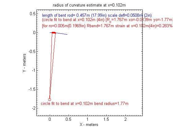
For an outside radius of 5 mm that would give a strain value of .28% for your small (11%) relative deflection value. That is well below the expected strain failure of around 1.5%, and the expected ovalization factor would have been too small to measure.
That would say your deflection must have been much larger than the .0508m (2in) value you measured. Otherwise the blank should not have failed unless there was a defect at that point.
Gordy
"Flyfishing: 200 years of tradition unencumbered by progress." Ralph Cutter
Who is online
Users browsing this forum: No registered users and 1 guest