
I just measured an old broken blank to confirm how much ovality could be measured prior to breakage.
I got .002 without failure, but pushing slightly more the mikes became loose but then the blank snapped. No warning. The blank dia was .335 with approx 70% open area. Deflection force was still moderate. How much deflection has been measured by competition casters ???
My initial measurements were actually .0008 and I rounded to .001. Good micrometers are a necessity for measurements this slight. An indicator with .0001 resolution would be a better choice if it can be affixed to the grip.
PLEASE NOTE: This is the Archived Sexyloops Board from years 2004-2013.
Our active community is here: https://www.sexyloops.co.uk/theboard/
Our active community is here: https://www.sexyloops.co.uk/theboard/
Effect of taper on spring nonlinearity - How does taper impact the k3/k1 ratio?
-
Eugene Moore
- IB3 Member Level 1
- Posts: 93
- Joined: Wed Jul 06, 2011 1:27 am
- Location: Missouri
- Contact:
-
gordonjudd
- IB3 Member Level 1
- Posts: 2214
- Joined: Mon Jul 10, 2006 12:14 am
- Location: California
- Contact:
Are you saying that I'm saying this Gordy?
Magnus,
No.
If you have read any of the back and forth posts on the Brazier effect on the non-linear spring characteristics of a fly rod you would know I was talking about some of Vince and Walter's claims. The example given was from Vince.
"can you explain that statement?
Good approach.
I think my repeated response was more along the lines of "Can you show some data or analysis to support that statement?" I don't think that is unreasonable request in a technical forum.
Do you think technical breadth should not be a factor in being a moderator in a technical forum?
and
I think this question is a fair example of your debating tactics, and goes some way to explain why this forum is falling flat on its face Gordy.
In that case what did you mean by:
it doesn't even mean expert in the field.
You will find that engineers take statements like that quite literally. I took it to mean that a moderator in a technical form did not need to be an expert in the field. As I said in my response I don't think that Merlin and I are experts (read the Gatti-Bono or Goriely papers to see what an expert in the field might be) but do think we "share a broader understanding of the physics of casting than most." Your opinion of that assessment might differ however.
If I got the wrong impression on what "does not mean an expert in the field was suppose to imply, then what did you intend it to mean?
Gordy
"Flyfishing: 200 years of tradition unencumbered by progress." Ralph Cutter
-
Magnus

- IB3 Member Level 1
- Posts: 12097
- Joined: Sat Oct 02, 2004 2:00 am
- Location: Banff, Scotland
- Contact:
Gordy
Take this thread as an example.
Do you consider yourself an expert in this field? Since you have described yourself (and everyone except Merlin) as 'chumps' and lacking the 'technical chops' for this one I take it you don't consider yourself an expert on this topic - yet you have acted as a mod for this thread.
Now, is it clear Gordy? You do not need to be THE expert or even AN expert in a field to moderate a forum. (I hope you realise I'm deleting the colourful four letter words from my posts in an attempt to remain civil )
)
I'm sure some engineers will. I'd love to read your data which says ALL engineers will take that literally. I need...ooooh...one engineer who did not take that literally or one engineer who agrees that the moderator need not be an expert in the field to refute that assertion. Would you like to guess what you need to support your thesis?
I think you and Merlin differ in significant ways.
Magnus
Take this thread as an example.
Do you consider yourself an expert in this field? Since you have described yourself (and everyone except Merlin) as 'chumps' and lacking the 'technical chops' for this one I take it you don't consider yourself an expert on this topic - yet you have acted as a mod for this thread.
Now, is it clear Gordy? You do not need to be THE expert or even AN expert in a field to moderate a forum. (I hope you realise I'm deleting the colourful four letter words from my posts in an attempt to remain civil
You will find that engineers take statements like that quite literally.
I'm sure some engineers will. I'd love to read your data which says ALL engineers will take that literally. I need...ooooh...one engineer who did not take that literally or one engineer who agrees that the moderator need not be an expert in the field to refute that assertion. Would you like to guess what you need to support your thesis?
I think you and Merlin differ in significant ways.
Magnus
Casting Definitions
"X-rays will prove to be a hoax."
"Radio has no future."
"Heavier than air flying machines are impossible."
Lord Kelvin
"X-rays will prove to be a hoax."
"Radio has no future."
"Heavier than air flying machines are impossible."
Lord Kelvin
-
gordonjudd
- IB3 Member Level 1
- Posts: 2214
- Joined: Mon Jul 10, 2006 12:14 am
- Location: California
- Contact:
I just measured an old broken blank to confirm how much ovality could be measured prior to breakage.
I got .002 without failure, but pushing slightly more the mikes became loose but then the blank snapped.
Eugene,
Thanks for taking the time to get more measured data. Did it break cleanly at one point (most likely due to a defect) or did it show the effects of a de-lamination failure in the middle of the bending radius that Tim Rajeff describes as a "good" material strain failure of around 2%.
For a 2% strain in a cross-section with the dimensions you describe (r_outside=4.25 mm r_inside=3.55mm thickness=.7mm) with an E_L/E_t ratio of 15 I get an expected ovalization factor of .019 using Merlin's simplified set of equations. That would produce a radius change of (4.25- 4.25*(1-.019))=.081 mm. Which is about .32 mil if I have done the conversions correctly. That is about .32/1 or one third the value you measured.
How did you put that much strain into the clamped butt section that failed? Was it clamped horizontally with a big tip load to get a strain value near the butt of 2%? Did you note the minimum bending radius when it failed? To get a 2% strain the bending radius would only be .2m, unless you were bending it around a solid form or focus point as Tim Rajeff describes here.
Deflection force was still moderate. How much deflection has been measured by competition casters ???
Here is a photo of the minimum bending radius near the tip for one of Lasse's distance casts while he was carrying 80 feet of line on a 5 wt rod.
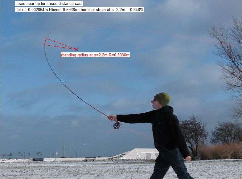
You can see the strain at that point was around .35% for that pull angle of around 40 degrees. Smaller pull angles will move the minimum bending radius nearer the tip of the rod during casting as compared to the point where the minimum bending radius is achieved for the 50% deflections and 90 degree pull angle Merlin assumed for his ovalization factor estimates.
However those bendforms are a long way from the shape needed to produce the minimum bending radius required to exceed the strain limit in a 3 wt rod. as shown below.
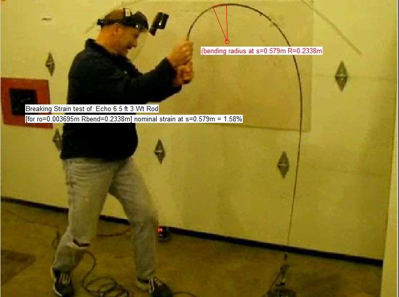
What do you mean by a moderate deflection force? Did the bendform prior to breaking look like the inverted U shapes that are shown on the Echo site when they perform break tests on their blanks? You can see it takes a lot of tip force and small pulling angles to get 2% strains in the butt section of most rods.
You will see a similar bend with a strain failure in this video of an echo 8 wt rod where the tip load was 15 lbf (66 N) at a pulling angle that appears to go negative before it breaks. Thus in that rod it took a huge tip force applied at a small pulling angle to break it.
It took a fork lift for Tim Rajeff to put that kind of stain on a 10 wt rod, so I don't think you will get near 2% strains in a rod while casting.
Gordy
"Flyfishing: 200 years of tradition unencumbered by progress." Ralph Cutter
If you have read any of the back and forth posts on the Brazier effect on the non-linear spring characteristics of a fly rod you would know I was talking about some of Vince and Walter's claims. The example given was from Vince.
I think my repeated response was more along the lines of "Can you show some data or analysis to support that statement?" I don't think that is unreasonable request in a technical forum.
Of course this all sounds great until you view what happened in practice. He received some data, realised he was wrong and put me on "IGNORE". But as I mentioned previously, that is the way that Gordy achieves consensus.
For those that have some confidence in physics principles, I recommend this reference to understand the linkage between beam deflection and beam deflection strain:
http://www.ecourses.ou.edu/cgi-bin....=theory
It appears that Magnus is now joining me in the naughty corner. So I will stock up the virtual beer fridge while Gordy uses his model to prove the real world is wrong as I am sure we will get some more visitors soon. I think evens on Walter getting ignored and 4/1 on Eugene being next.
Merlin
Thank you for for sight of your model it looks very impressive and I commend your efforts. I intend to wait and see what the outcome of this thread is before doing any work, as looking at the exchanges it would appear that any response will be met with the usual barrage and I have no practical use for the data.
However, if you have some data for composite matrix failures, please can you pass them to Gordy so that he can see the load exceeding the rod hoop strength is the usual failure cause and not the fibre being ripped apart lengthways within the matrix.
In a normal world turning the discussion to ovalisation would be a beneficial thing because you are drawing on the collective knowledge of board members with a wide range of knowledge and experience and everyone would benefit from this cross-fertilisation.
The Brazier effect is real and should have been looked at in a considered way. Instead it was rubbished by Post 12 without any data or analysis work being done. After that the positions have entrenched between the 2 sides.
For those of us that believe it plays a part it appears that the subsequent analysis has been aimed at making sure the initial reaction was not wrong, rather than trying to find out if there was any mileage in the premise. I have asked why ovalisation is being modelled at the butt instead of the at the other end of the rod where the bend radius of curvature is smallest and the brazier effect most likely to be felt. This point is shown as being at 2m from the butt in the model conditions that you have provided.
I have not received any answer to that question, although I have posed it many times. However, it is fundamental to any analysis. From my side of the trenches, it appears that the thread has been about making sure the moderators are not wrong rather than trying to find out the right answer.
I have put myself firmly in the "chump" corner even though I have formally studied structures. This is because I have worked with some seriously clever people on this sort of technology such as helicopter rotor systems designers. My role was to conduct the practical validation tests of their hugely complex composite structural models. So I have an inkling of how much we are just scrabbling at the fringes of the subject.
My guess is that you did not get a reaction to your cane question because there are not many people on the board who share your interest. I have built and modified fibre glass and graphite rods and so kept quiet waiting to see if there was anyone more knowledgeable about bamboo. I cannot answer your question but this article does go some way explaining the mechanics:
http://www.springerimages.com/Images....936-8-2
I have no strong feeling about whether this section stays open or not but I can get access to other resources to help me if needs be. It would be be a shame if it died but it might be the kindest thing to shoot it.
Personally, I would prefer if it was wound back to how it used to be in the older threads, where there were many knowledgeable technical and non-technical contributors who joined in the discussion. In recent times, there has only been tumbleweed blowing through here. There were many contributors such as Grunde and Torsten that I would like to learn from as well as people who have been involved in rod development out there who can tell you what really happens and their voices are no longer heard.
Vince
Thank you for for sight of your model it looks very impressive and I commend your efforts. I intend to wait and see what the outcome of this thread is before doing any work, as looking at the exchanges it would appear that any response will be met with the usual barrage and I have no practical use for the data.
However, if you have some data for composite matrix failures, please can you pass them to Gordy so that he can see the load exceeding the rod hoop strength is the usual failure cause and not the fibre being ripped apart lengthways within the matrix.
The purpose of this particular thread was to draw attention of the (positive) effects of non linearity of rods. For some reason, the discussion turned about: is the non linearity linked to ovalization? I did not bring that in, but tried to check if this was real. My last example with cane rods does not bring any reaction, although cane rod makers argue about the advantage of their rods regarding to ovalization. I am not going to ask why once more.
In a normal world turning the discussion to ovalisation would be a beneficial thing because you are drawing on the collective knowledge of board members with a wide range of knowledge and experience and everyone would benefit from this cross-fertilisation.
The Brazier effect is real and should have been looked at in a considered way. Instead it was rubbished by Post 12 without any data or analysis work being done. After that the positions have entrenched between the 2 sides.
For those of us that believe it plays a part it appears that the subsequent analysis has been aimed at making sure the initial reaction was not wrong, rather than trying to find out if there was any mileage in the premise. I have asked why ovalisation is being modelled at the butt instead of the at the other end of the rod where the bend radius of curvature is smallest and the brazier effect most likely to be felt. This point is shown as being at 2m from the butt in the model conditions that you have provided.
I have not received any answer to that question, although I have posed it many times. However, it is fundamental to any analysis. From my side of the trenches, it appears that the thread has been about making sure the moderators are not wrong rather than trying to find out the right answer.
I have put myself firmly in the "chump" corner even though I have formally studied structures. This is because I have worked with some seriously clever people on this sort of technology such as helicopter rotor systems designers. My role was to conduct the practical validation tests of their hugely complex composite structural models. So I have an inkling of how much we are just scrabbling at the fringes of the subject.
My guess is that you did not get a reaction to your cane question because there are not many people on the board who share your interest. I have built and modified fibre glass and graphite rods and so kept quiet waiting to see if there was anyone more knowledgeable about bamboo. I cannot answer your question but this article does go some way explaining the mechanics:
http://www.springerimages.com/Images....936-8-2
I have no strong feeling about whether this section stays open or not but I can get access to other resources to help me if needs be. It would be be a shame if it died but it might be the kindest thing to shoot it.
Personally, I would prefer if it was wound back to how it used to be in the older threads, where there were many knowledgeable technical and non-technical contributors who joined in the discussion. In recent times, there has only been tumbleweed blowing through here. There were many contributors such as Grunde and Torsten that I would like to learn from as well as people who have been involved in rod development out there who can tell you what really happens and their voices are no longer heard.
Vince
-
Hal Jordan

- IB3 Member Level 1
- Posts: 604
- Joined: Thu May 05, 2011 1:17 am
- Contact:
Gordy - do you know what a sanity check is? That's when engineers (I'm not one by the way) look at something like your measurements and do a bit of hand waving to see in your calculations make any sense. For instance, you had Matthias as a 10 foot high Viking. Now you have Tim Rajeff as roughly 4' 3.5" tall. I've met Tim. He's not a 10 foot viking but I don't think he's Papa Smurf either.
-
Hal Jordan
- IB3 Member Level 1
- Posts: 604
- Joined: Thu May 05, 2011 1:17 am
- Contact:
Vince,
Thanks for posting this link. I had thought of posting it earlier as well so we could discuss Gordy's assertion that angle of deflection is not important. I guess now would be a good time.
I'm sorry for hand waving here but can anybody identify the assumptions that are made in this image?

1. The neutral line does not compress or stretch, i.e. it remains the same length during bending. This is true if the material is isotropic. If not then it is true for limited amounts of bending.
2. The material in the beam reacts the same to tension as it does to compression. This is acceptable for small amounts of bending or if the beam only bends in a circular fashion on all edges.
3. Ovalization does not occur during the bending. Also true for small amounts of bending...
Seems to be a common thread - true for small amounts of bending. How small? It depends on the material. If the material is infinitely elastic and we assume that it always bends in a circular fashion the bend can be 360 degrees and the radius can be quite small.
If the material is not infinitely elastic or does not respond equally to compression and tension what happens? The bend radius of the inside, neutral, and outside lines of the bend will not be equal. That would mean that the lines AB and A'B' could not be described using a single radius of curvature, ρ, and single differential angle, dθ.
Let's look at the case where ovalization does begin to occur. What does this look like? It could look like a lot of things but in some cases it will simply look like the bend radius if the inside edge of the beam, the line A'B' in the picture, has a smaller bend radius than the neutral axis. The length of the neutral axis still remains as ρdθ but now the length of A'B' is (ρ-x)dΘ where x is y minus an ovalization factor and Θ is the deflection angle for the circle approximating the inner edge.
so strain is now:
ε = ((ρ-x)dΘ - ρdθ)/ρdθ = (ρdΘ-xdΘ - ρdθ)/ρdθ
Again - this model has limited application as described previously. If we can represent the inner axis as a curve other than a circle we can then use a common angle of deflection for both curves but we would not likely be able to eliminate the angle of deflection from the resulting equation for strain.
Thanks for posting this link. I had thought of posting it earlier as well so we could discuss Gordy's assertion that angle of deflection is not important. I guess now would be a good time.
I'm sorry for hand waving here but can anybody identify the assumptions that are made in this image?
1. The neutral line does not compress or stretch, i.e. it remains the same length during bending. This is true if the material is isotropic. If not then it is true for limited amounts of bending.
2. The material in the beam reacts the same to tension as it does to compression. This is acceptable for small amounts of bending or if the beam only bends in a circular fashion on all edges.
3. Ovalization does not occur during the bending. Also true for small amounts of bending...
Seems to be a common thread - true for small amounts of bending. How small? It depends on the material. If the material is infinitely elastic and we assume that it always bends in a circular fashion the bend can be 360 degrees and the radius can be quite small.
If the material is not infinitely elastic or does not respond equally to compression and tension what happens? The bend radius of the inside, neutral, and outside lines of the bend will not be equal. That would mean that the lines AB and A'B' could not be described using a single radius of curvature, ρ, and single differential angle, dθ.
Let's look at the case where ovalization does begin to occur. What does this look like? It could look like a lot of things but in some cases it will simply look like the bend radius if the inside edge of the beam, the line A'B' in the picture, has a smaller bend radius than the neutral axis. The length of the neutral axis still remains as ρdθ but now the length of A'B' is (ρ-x)dΘ where x is y minus an ovalization factor and Θ is the deflection angle for the circle approximating the inner edge.
so strain is now:
ε = ((ρ-x)dΘ - ρdθ)/ρdθ = (ρdΘ-xdΘ - ρdθ)/ρdθ
Again - this model has limited application as described previously. If we can represent the inner axis as a curve other than a circle we can then use a common angle of deflection for both curves but we would not likely be able to eliminate the angle of deflection from the resulting equation for strain.

Vince
Although I promised myself not to contribute anymore until I get some data to be shared, I’m going to make a few comments.
At the same time, the thread is improving (although we are discussing about something else that non linearity of rod spring), but the atmosphere remains heavy.
Gordy is aware of the different ways a composite can fracture. He relies on Tim’s experience which illustrates (without any scale effect) a breakage for a small radius of curvature. A raw estimate is that the breakage occurs for a strain close to the compression limit of the material. It is then not so wrong to assume that ovalization took little place in this failure. If you look at the last video link posted by Gordy, you can appreciate how strong is the blank which is certainly not made without proper design (which can explain why compression failures can be “things of the past” for some manufacturers).
On the other side of the spectrum, Eugene’s experience with another rod indicates a failure for a lower limit (estimates: 0.6% ovalization, strain 1.2% guessed from dimensions for a supposed to be low quality graphite composite), which means compression failure is real in some cases, explaining also the opinion of some manufacturers on the issue.
For the time being, we have used an assumption corresponding to the Brazier conditions to estimate ovalization, which means the beam is infinite and not constrained at the lower part of the butt. This is wrong for the lower part of the rod of course, and one objective is to handle this difficulty. I hope to get some clues from the computing center; I have some from literature which may fall short. In the example I sent you, even if maximum strain is in the tip area, the dimensions of the sections (particularly the wall thickness) do not lead to the maximum ovalization. In the best “scenario” I got from literature, the worst conditions occurs somewhere in the mid butt. Now I’m waiting for the run of the computing center to tell us where the best estimate can be.
I agree that this forum would beneficiate from the contribution of people who are likely more knowledgeable than vets like me. It is up to them to “take the power” and give the best information to progress. I really do not care if I am wrong at the end, but we need something consistent. Maybe the effort takes too much of their time. This is what happened to me during the last weeks: too much of my time and I have to stop this.
Walter
Equations are not visible in your mail; this occurs since the ikonboard does not like them very much, you have to type them with the normal keyboard of your computer. Last time you asked me where the characteristics of the composite (Celion 3000 Narmco) I use come from: they come from a book on composite structures, the characteristic where measured for a fiber content of 62% (unidirectional). I took that to have an “old” material more subject to ovalization. Then we shall see.
I’m not sure that because there is a difference between tension resistance and compression resistance, then the material ovalize. Its ovalization will depend first on its design (wall thickness and radius). It will break by compression because it is its weakness, and not by tension, but it can ovalize before these limits are obtained.
If properly designed (ex Echo), then there is the possibility to contain ovalization up to the mechanical compression resistance. If not, (Eugene’s blank?), it can fail before this limit. This corresponds to the situation described in the Ohnishi paper (I just have it in print, not in pdf), where the rod breaks for 0.6% to 0.7% strain (looks like Eugene’s experience). The picture of the bended rod looks like Tim’s Rajeff video: a big angle with horizontal for the butt (73 degrees if I remember well), while the mechanical limit was given at 1% (there was a glass scrim incidentally). It broke above the butt (at some 25% of rod length). The authors used the Brazier limit too, although illustrated curves do not go down to the very end of the butt, which remembers me my assumptions.
Merlin
Fly rods are like women, they wont´play if they're maltreated.
Charles Ritz, A Flyfisher's Life
Charles Ritz, A Flyfisher's Life
-
gordonjudd
- IB3 Member Level 1
- Posts: 2214
- Joined: Mon Jul 10, 2006 12:14 am
- Location: California
- Contact:
Gordy - do you know what a sanity check is? That's when engineers (I'm not one by the way) look at something like your measurements and do a bit of hand waving to see in your calculations make any sense. For instance, you had Matthias as a 10 foot high Viking. Now you have Tim Rajeff as roughly 4' 3.5" tall.
Walter,
You are correct, that drawing is not scaled properly. Thanks for your a sanity check. I will see where I went wrong in the pixel to meter conversion factor used in that photo.
We can correct the values in that photo to get estimates for the real values by assuming Tim is around 6 feet tall. That means the bending radius was actually .18*6/4.5=.24 m. With an outside radius of 4mm at that point that would give a strain value of .004/.24=1.67%. That value is closer to the one Merlin uses for his strain limit value.
Thanks for the correction. I will get a properly scaled photos posted later in the week when I find my bug.
I had thought of posting it earlier as well so we could discuss Gordy's assertion that angle of deflection is not important.
I don't think I said the angle was not important. If you look at that post again I said,
As a warning it has nothing directly to do with an angle you might measure at some point along the rod like measuring the AA of a rod in Bill's CCS approach.
And that statement is true. As noted in a later post, the strain at some point cannot be directly determined by measuring its deflection angle. It is the derivative of the angle of deflection with respect to the independent length factor that determines the bending radius (1/r=dphi/ds). Thinking it depends on the angle is equivalent to saying measuring an objects position will tell you what its velocity is.
That's when engineers (I'm not one by the way)
That confirms a suspicion I have had for a long time. Does that mean you never took a dynamics or strength of materials class?
Gordy
"Flyfishing: 200 years of tradition unencumbered by progress." Ralph Cutter
-
Hal Jordan
- IB3 Member Level 1
- Posts: 604
- Joined: Thu May 05, 2011 1:17 am
- Contact:
Merlin,Merlin wrote:Walter
I’m not sure that because there is a difference between tension resistance and compression resistance, then the material ovalize. Its ovalization will depend first on its design (wall thickness and radius).
I will try to put pictures together for a better explanation when I have time. In the meantime if you refer to
this picture
Figures d and g illustrate what happens when we do not have infinite elasticity. The buckling results when the ability of the material to compress farther is exceeded. In this case we can't simply use the formula based on bend radius vs tube radius to calculate strain. That formula would be totally valid for figures c and f however. Perhaps I ask about limits and assumptions too much but this is an illustration of why I find them important. Perhaps the confusion comes from the fact that you are on step 107 of your analysis (running the model) and I'm still back at steps 5 and 6 (defining the model). :p
With respect to your question about bamboo - sorry for not responding. I didn't realize you took the lack of response as lack of interest. It was a fair question and is one that should be answered. I simply don't know anything about it. I'll see if I can find anything in research.
-
Hal Jordan
- IB3 Member Level 1
- Posts: 604
- Joined: Thu May 05, 2011 1:17 am
- Contact:
Merlin
You are correct but
the distortions and drivel continues. As does modifying his own posts after other people have posted their response. I shall put him on IGNORE to reduce the background noise and to keep the conversation civil.
However, let's press on:
Tims experience is indicative of a static loading failure and that may have been appropriate for that particular demonstration but should not be used in all cases.
Dynamic loading leads to different failure mechanisms. There are generally considered to be six failure mechanisms of fibre composites due to compressive loads. The matrix failure that I mentioned, fibre crushing, the tube splitting from one end, de-lamination (caused by elastic buckling), elastic buckling, and plastic micro-buckling. However, to my mind they are all symptoms of matrix failure. I have never seen the plastic micro-buckling but I have seen the end split on a Gatti blank and de-lamination on composite panels. I have also seen elastic buckling of a wing as a result of flight test incident.
As you are aware different materials are used throughout a rod for different effects and a low strain matrix may be designed in for a particular purpose. It is something that we have not really delved into. The Harrison website does provide a list of possible materials and there are quite wide variations in the strain rates, although all of them are below 2%. Of course a designer in his right mind would not design to his limit load for normal use:
http://www.harrisonrods.co.uk/production.htm
There are a couple of statements in there that catch my eye, such as:
I am not sure how we can work around this to get sensible values for calculations. I think that Emory Harry measures the MoE values but I do not know his methods. Until this is understood, I think that there will always be a lot of room for debate.
Going back to Brazier:
This may explain why we have been at cross purposes. I have been looking at Chapter 6 of the Tatting thesis you provided which deals with finite length cylinders for isotropic and orthropic construction. I'd assumed you had also been using that reference.
He considers both structural and material properties when considering whether ovalisation was occuring. In particular I looked at equation 6.22 and the accompanying statement that:
The latter was the construct I was assuming for the lower half of the rod because your D/t analysis shows that section of the rod to be thick walled. I had considered using the equation as a guideline but was not confident of the material values. Perhaps our positions are not so far apart.
Vince
At the same time, the thread is improving (although we are discussing about something else that non linearity of rod spring), but the atmosphere remains heavy.
You are correct but
And that is true, the strain at some point cannot be determined by measuring its deflection angle. It is the derivative of the angle of deflection with respect to the independent length factor that determines the bending radius. Thinking it depends on the angle is equivalent to saying measuring an objects position will tell you what its velocity is.
the distortions and drivel continues. As does modifying his own posts after other people have posted their response. I shall put him on IGNORE to reduce the background noise and to keep the conversation civil.
However, let's press on:
Gordy is aware of the different ways a composite can fracture. He relies on Tim’s experience which illustrates (without any scale effect) a breakage for a small radius of curvature.
Tims experience is indicative of a static loading failure and that may have been appropriate for that particular demonstration but should not be used in all cases.
Dynamic loading leads to different failure mechanisms. There are generally considered to be six failure mechanisms of fibre composites due to compressive loads. The matrix failure that I mentioned, fibre crushing, the tube splitting from one end, de-lamination (caused by elastic buckling), elastic buckling, and plastic micro-buckling. However, to my mind they are all symptoms of matrix failure. I have never seen the plastic micro-buckling but I have seen the end split on a Gatti blank and de-lamination on composite panels. I have also seen elastic buckling of a wing as a result of flight test incident.
On the other side of the spectrum, Eugene’s experience with another rod indicates a failure for a lower limit (estimates: 0.6% ovalization, strain 1.2% guessed from dimensions for a supposed to be low quality graphite composite), which means compression failure is real in some cases, explaining also the opinion of some manufacturers on the issue.
As you are aware different materials are used throughout a rod for different effects and a low strain matrix may be designed in for a particular purpose. It is something that we have not really delved into. The Harrison website does provide a list of possible materials and there are quite wide variations in the strain rates, although all of them are below 2%. Of course a designer in his right mind would not design to his limit load for normal use:
http://www.harrisonrods.co.uk/production.htm
There are a couple of statements in there that catch my eye, such as:
These fibre types vary in properties when they are tested on their own, putting them into a composite structure complicates everything and the strength and stiffness becomes more dependent on the fibre orientation and resin properties
I am not sure how we can work around this to get sensible values for calculations. I think that Emory Harry measures the MoE values but I do not know his methods. Until this is understood, I think that there will always be a lot of room for debate.
Going back to Brazier:
For the time being, we have used an assumption corresponding to the Brazier conditions to estimate ovalization, which means the beam is infinite and not constrained at the lower part of the butt. This is wrong for the lower part of the rod of course, and one objective is to handle this difficulty. I hope to get some clues from the computing center; I have some from literature which may fall short.
This may explain why we have been at cross purposes. I have been looking at Chapter 6 of the Tatting thesis you provided which deals with finite length cylinders for isotropic and orthropic construction. I'd assumed you had also been using that reference.
He considers both structural and material properties when considering whether ovalisation was occuring. In particular I looked at equation 6.22 and the accompanying statement that:
Therefore, for a given material system, low values of l (which produce very little Brazier effect) are generated by short and thin cylinders, and buckle according to the classical solution. Longer and thicker cylinders, which are more easily construed as “tubes”, undergo drastic Brazier nonlinearity before buckling occurs.
The latter was the construct I was assuming for the lower half of the rod because your D/t analysis shows that section of the rod to be thick walled. I had considered using the equation as a guideline but was not confident of the material values. Perhaps our positions are not so far apart.
Vince
-
Hal Jordan
- IB3 Member Level 1
- Posts: 604
- Joined: Thu May 05, 2011 1:17 am
- Contact:
Vince,VGB wrote:the distortions and drivel continues. As does modifying his own posts after other people have posted their response.And that is true, the strain at some point cannot be determined by measuring its deflection angle. It is the derivative of the angle of deflection with respect to the independent length factor that determines the bending radius. Thinking it depends on the angle is equivalent to saying measuring an objects position will tell you what its velocity is.
Thanks for pointing that one out. I had dismissed the post as the usual drivel when I saw the comments about my education.
Gordy - First of all - you do know what a derivative is don't you? Second, as usual, I provide input regarding strain calculation and you discredit it by saying it was actually about bend radius. Then you follow it up with a comment about my education.
The rest of us are trying very hard to be civil while you continue to try and stir up more crap. Grow up.
Walter
(d) and (g) look like micro/local buckling (reknowned to occur before buckling). It is again a failure by compression, but I am not sure that you need to be at the limit of compression to observe it. It is still a question for me. When I read the paper on electrical poles, the weakest one failed for a low force and low curvature and a large ovalization: it took a significant increase in force at tip to get the failure after the section started to ovalize, this is why I suspect ovalization to start before the compression limit is reached.
Vince,
I shall give another look to Tatting on the chapter 6. Maybe I shall find more inspiration for the case of a clamped butt.
The link to Harrison rods is interesting, I guess several manufacturers would say the same: yes, they use multi modulus multi layers techniques and it is a nightmare to estimate the transversal modulus from that. The longitudinal one is accessible by computing.
I am off for a few days from tomorrow noon.
Back in the middle of next week.
Merlin
Fly rods are like women, they wont´play if they're maltreated.
Charles Ritz, A Flyfisher's Life
Charles Ritz, A Flyfisher's Life
Who is online
Users browsing this forum: No registered users and 0 guests