Here is a picture from Theo Matschewsky's site, that shows what I mean:
Torsten,
I may be missing something using Google translator on Theo's site, but are those black winding made from carbon fiber rather than the size A wrapping thread that you use?
For my own builds I'm wrapping the entire length of the ferrule with size A thread and I've not had so far problems there (I'm doing this also because I've less trouble with loose sections).
I can see how that would give some added strength to bursting the ferrule from outward directed forces, but do they provide some increase in the torsional stiffness as well?
Is torsion tested at all ?
I have never seen any torsion failure tests, but in his patent for making rods with a trapezoidal cross-section Gary Loomis says:
Steve Rajeff said Fenwick used to torture test their rods by angling the butt at 45 degrees and then hanging a piece of chain from the tip to get a sizeable deflection. The butt was then rotated and the number of cylcles it took to get a fatigue failure were counted. Fiber glass rods survived for several hundred thousand rotations, and Steve thought that graphite rods would surpass that mark, although he was not aware a company actually doing that sort of fatigue test on graphite blanks.
I do think that blanks fatigue in more subtle ways with use. I have measured changes in the natural frequency of one of my rods over a few years of use.
Gordy
"Flyfishing: 200 years of tradition unencumbered by progress." Ralph Cutter
I can see how that would give some added strength to bursting the ferrule from outward directed forces, but do they provide some increase in the torsional stiffness as well?
This surely depends on the acting forces that the torsion generates. You're right it will help only against outward directed forces. Usually a wrapping is recommended by many blank manufacturers (against splitting of the blank ends). It looks like Theo uses graphite rowing for this purpose, I'll try this for my next build. Perhaps kevlar thread should do this job as well.
BTW I have a Sage RPL+ #5 4pcs. blank - there Sage has still done these wrappings of the ferrule area.It seems that they have later removed that from the design to save some weight?
Bye,
Torsten
^^ Warning: The above text contains misspellings, grammatical errors and of course nonsense.
We have left the ovalization issue for "how to get rid of shear stress?".
Maybe the technique used on Theo's rod is effective, but it does not look beautiful. The tip seem to have inherited from another section of higher diameter.
An old trick: never overbridge a ferrule.
Merlin
Fly rods are like women, they wont´play if they're maltreated.
Charles Ritz, A Flyfisher's Life
BTW I have a Sage RPL+ #5 4pcs. blank - there Sage has still done these wrappings of the ferrule area.
Torsten,
Were those wrappings done with the same winding thread that was used on the guides? If so I would think it was done with the intent of providing more resistance to outward forces that might split the ferrule. One book that I have recommends winding the female ferrule as the first step in building the rod so that the ferrule will be stronger and be less prone to splitting when the rod was assembled and bent to find the spine. That might have have been a hold over from earlier times when the hoop strength of rods was less than it is now.
However, since winding thread will stretch it probably does not do as much in stiffening the ferrule against outward forces as you might think. You can see the thread stretched and lifted from the blank underneath both cracks in Paul's photo. So whatever strength they provided was not enough to handle the stresses at the ferrule he produces with twisted out guides.
You idea of using Kevlar or Theo's use of carbon fibers would provide more hoop strength than just using winding thread as I have traditionally done. Theo's carbon fibre reinforcement approach is not very pretty, but it works.
It seems that they have later removed that from the design to save some weight?
That is a question for Sage to answer, but I expect they decided the wraps were no longer needed because they now have better hoop strength in their ferrule designs.
Spolek found that adding weight near the tip will impact its frequency much more than it does when placed further down the rod. Thus I don't think that the added weight from ferrule wraps would impact the frequency nearly as much as using a heavier tip top.
I would suggest experimenting with Kevlar on a cheap blank first as I suspect that it it may damage the blank under load.
Vince,
Can you expand on why you "suspect" no stretch wraps would damage the rod? Theo has been using carbon fiber wraps to repair rods with good results for years. I would think they would have even less stretch than Kevlar so I do not know how they might damage the rod when it undergoes a heavy load.
Gordy
"Flyfishing: 200 years of tradition unencumbered by progress." Ralph Cutter
Merlin,
Does that mean you would recommend not reinforcing the ferrule with some sort of wrapping?
Have we left the ovalization issue for "how to get rid of shear stress?".
It appears so for now (a Sexyloops tradition of changing horses in mid-stream), although I think understanding the impact of shear stresses is just as complicated as putting some values on ovalization.
In regards to the latter, could you address some of questions Vince raised in Post #60 regarding your earlier statement about:
For the graphite rod, ovalization achieves 1.2% and the effect on tip position is about an 8% change in vertical position (lower).
I think you halved both the inside and outside diameters at the tip in that simulation. If you keep the wall thickness the same as before, I think you get much smaller ovalization values in that case. For the thicker wall thicknesses that are actually used in rods (r/t ratios of 3-5 at the butt not the factor of 9 used in the Abacus model) would reduce that ovalization factor even more.
Also since you you tilted the rod vertically and applied a horizontal load that change in vertical position is equivalent to changing the x tip position in the normal case where the load is pulling down on a rod whose butt is pointed horizontally. We normally do not worry about the change in the x position as the y deflection is used to calculate the spring constant of the rod.
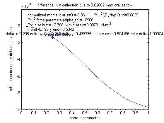
I thought your later calculations were more in line with my results for the thicker tipped Abacus model, where a 10x increase in the .2% ovalization predicted by the Abacus model ( to get a 2.0% max ovalization from a 90 degree pull angle) only increased the y deflection by 1% as shown below. For the actual ovalization factor of .2% that change would also go down by an order of magnitude to .1% which would put the impact of ovalization in the measurement uncertainty range.
A 2% max ovalization factor resulting in a 1% increase in the perpendicular tip deflection is much different than a 1.2% ovalization resulting in an 8% change , and gives more support to your conclusion that:
although it exists, ovalization of graphite rod is a red herring in terms of consequences.
Gordy
"Flyfishing: 200 years of tradition unencumbered by progress." Ralph Cutter
Torsten,
The use of Kevlar for the ferrule wrap is a great idea.
Even if only for a short trim band this would increase the resistance to ovalization of the female ferrule.
Do you have any sources of kevlar thread with out lubricants ?
Gordon,
The haul exerts tension in the fly line to the stripper guide, restrained by the casting grip. In one, two or three piece rods the stripper guide is located on the butt section of the blank meaning all the forces are carried thru that section.
The tension from the haul exerts multiple directional forces on the stripper guide and depends upon angle from the guide and guide angle from the rod flex plane. These forces can create tension, torsion and compression as they're compound angles from the rod plane and the tangent of the instantantious arc radius at the stripper guide location. Rotation of the guide in 90 resiults in virtually all tension stress unless the haul is in plane and tangent.
With the guides at 6 o'clock the forces are high torsion unless the haul is planar and tangent. If the guides are rotated 90 degrees out the forces from the haul are compressive unless the haul is planar and tangent.
The reason for relocating the stripper guide closer to the ferrule is to reduce the cantilever with the butt section thru the ferrule.
I assume these are factory build rods rather than custom.
Factory build for the TCX is a stripper guide at 79.3 inches. The factory for the TCR was at 77.5 . The TCX has the stripper relocated closer to the ferrule. Maybe accident maybe necessary.
The additional 2 inches I recommended was to simulate the factory build without changing the design intent.
The tension from the haul exerts multiple directional forces on the stripper guide and depends upon angle from the guide and guide angle from the rod flex plane.
Eugene,
I cannot visualize the angles you are talking about here. Also is the force that is producing the twisting moment related to the friction and pull angles of the line going through the guide?
I know Perkins talks about the effect of running the line through the guides has a different effect on the deflection of the rod as compared to pulling from just the tip. However, I have made force vs deflection measurements both ways, and at least for 90 degree pull angles see no measurable difference between the two cases.
I don't know if Perkins ever did a measurement to back up his claim that the line pull from the guides is going to cause a change in the perpendicular bending moment. It is hard for me to see that effect since aside from the tip top the pull angle of frictional forces in the guides is following the long axis of the rod, and also the sine(theta) component of the pull from the line tension is very small.
I can see that attaching the line to a guide would cause some torquing because that would be a direct pull, but for the small angle differences going through the guides and the fairly low friction forces between the guide and the line I don't see how it going to produce much twisting torque (or bending moment for that matter).
Could you make up a drawing showing what you are talking about? It is still not clear to me how T*sin(theta) where theta is the angle of the pull from the stripping guide relative to the blank and T is the line tension from the haul (T=mass of line*acceleration of line) is going to produce much of a difference in the bending or twisting of the lower two butt sections.
In Lasse's haul his hand acceleration was around 10m/s in .12 seconds. Assuming he was hauling about 20 grams of line that would produce a hauling force of only 10/.12*.02=1.6 Newtons. That is a fairly small force and if his pulling angle relative to the stripper guide was 10 degrees the perpendicular component of that force would be 1.6*sin(10)=.3 N. That is a fairly small perpendicular bending force especially since it is being applied to a strong butt section where the stripper guide is positioned.
Gordy
"Flyfishing: 200 years of tradition unencumbered by progress." Ralph Cutter
OK Gordon now you are beginning to follow my rational.
The forces are however much greater than you believe.
As the haul is started the direction is roughly tangent to the blank arc and roughly in plane with the arc of the rod.
This is a fleeting moment in time though as the haul must procede thru an arc down and across the body taking it both off plane and off tangent with the rod arc. The friction is much greater than expected because the angle is increasing rapidly as it occurs in 3-d.
The angle off tangent increases as the rod bends and rotates where the angle off plane is steadily becoming greater. This adds the sine function in both directions at the stripper guide which is not located on the butt section but seperated from it by a compression fit into the ferrule preloading the tension in the connection. At the finish of the haul the forces are almost perpendicular to the plane and the arc tangency.
Of course if ovality is a "red herring" in the terms of casting and haul forces are very low this must not be happening.
Paul quit stepping an your rods.
Of course this fails to explain the bursting of the wraps outward which can only follow the splitting of the female ferrule.
Why must models be expressed in 2-d and with linear tapers and as one piece construction when we live in a world where none of these exist ??
Perhaps I'm the one who is grammaticaly and verbally challenged.
Just have to live with it.
The classical recommendation is to wrap a guide on the female ferrule, that helps to reinforce it a little bit and avoids a higher level of stresses at that point (tension of the line in between guides).
Coming back to the simulation of a rod bended in nearly a half circle, the "8%" is linked to the position of the tip (with and without ovalization) measured from the butt and not from the original tip position. If I change for the latter, the change in deflection is less than 1% (8% for a one feet distance from the butt versus less than 1% if measure from more than 8 feet from original tip position).
Since the male ferrule is tightly in place, there is no chance to get an ovalization of the female ferrule (thicker overall wall). It has to support an internal pressure which tends tearing fibers apart. If you add a twisting condition, you tend to make fibers turn and slip along each other. In both case the weak point is the matrix (resin). That's an interesting point to document, but no time available for the moment.
Merlin
Fly rods are like women, they wont´play if they're maltreated.
Charles Ritz, A Flyfisher's Life
gordonjudd wrote:Can you expand on why you "suspect" no stretch wraps would damage the rod? Theo has been using carbon fiber wraps to repair rods with good results for years. I would think they would have even less stretch than Kevlar so I do not know how they might damage the rod when it undergoes a heavy load.
Wrapping with Kevlar is difficult because the lack of stretch makes it difficult to hold the tension so there is a tendency to overtighten the thread and potentially damage the blank. With that in mind, I would suggest that you use thread of similar physical dimensions to standard size A if you can find it.
Additionally, if you do not hold sufficient tension then there will be more of a tendency for shear between the layers and earlier onset of failure.
Once you remove, the capability for stress relief due to the more rigid wrap, another part of the rod will have to take up additional load to compensate, if it heads towards the tip, you may introduce another failure mode.
Personally, I would have a trial run on an inexpensive blank before trying it on an top end one.
I waited to ask this question because you kept changing your post again.
Can you expand on why you "think" your carbon fly rod is suffering from fatigue and impacting its frequency in a "subtle" way?
Merlin wrote:Since the male ferrule is tightly in place, there is no chance to get an ovalization of the female ferrule (thicker overall wall). It has to support an internal pressure which tends tearing fibers apart. If you add a twisting condition, you tend to make fibers turn and slip along each other. In both case the weak point is the matrix (resin).
Merlin
If I've understood you correctly then I disagree with your summary. The failure mode on the resin is fine but the female ferrule must be distorting for that failure to occur.
Can you expand on why you "think" your carbon fly rod is suffering from fatigue and impacting its frequency in a "subtle" way?
Vince,
Certainly.
If a rod is exposed to big bending moments (in my case it was from pulling the rod back too far in trying to land Silver Salmon quickly) it can break fibers in the laminate and/or induce slips in the resin holding those fibers together. This does not cause the catastrophic failure you see in the Rajeff videos, but a more subtle reduction in the rod stiffness over time. I imagine that exposing a rod to a few hundred thousand cycles on the Fenwick torture machine might cause some fatigue changes as well especially if a very heavy loading chain was involved.
The 8 wt rod I used went from having a natural frequency of 3.2 Hz when it was new to 2.67 Hz after being exposed to a few seasons of "abuse."
Looking at the rod softening thread I think a lot of people have seen similar subtle changes in their rods over a few seasons of use as well.
I waited to ask this question because you kept changing your post again.
When I re-read a post I often times find typos or think there is a better way of expressing an idea. Also if I made a error in a calculation or a note in a graph I will correct it.
I don't think I change the intent of my posts in that process, but do think it provides a better record for people that read a thread part way through and may not wade through pages of posts to see a data correction in a later post.
If someone produces some data that makes me change my mind about something I will say so in a later post..
Gordy
"Flyfishing: 200 years of tradition unencumbered by progress." Ralph Cutter
If you add a twisting condition, you tend to make fibers turn and slip along each other. In both case the weak point is the matrix (resin).
Merlin,
Just another expert opinion, but I think Theo would agree with you. He says:
Regarding the problem of broken ferrules on switch rods I agree with many others that this probably occurs due the twist created in the rod during casting.
Gordy
"Flyfishing: 200 years of tradition unencumbered by progress." Ralph Cutter
Regarding to ovalization, there is no difference between a male ferrule and a stiffener. So I cannot see the reason to assume there is more ovalization at this point of the rod shaft.
Merlin
Fly rods are like women, they wont´play if they're maltreated.
Charles Ritz, A Flyfisher's Life